 English
 Espaol
 Franais
 阿拉伯
阿拉伯 中文
中文 Deutsch
 Italiano
 Português
 日本
日本 韓國
韓國 български
 hrvatski
 esky
esky Dansk
Dansk Nederlands
 suomi
suomi Ελληνικ
 印度
印度 norsk
norsk Polski
 Roman
Roman русский
 Svenska
珀金斯Perkins1204E-E44TA(TTA)測試調(diào)整供應(yīng)商,珀金斯Perkins1204E-E44TA(TTA)測試調(diào)整技術(shù)價(jià)格規(guī)格咨詢服務(wù),珀金斯Perkins1204E-E44TA(TTA)測試調(diào)整零配件供應(yīng),珀金斯Perkins1204E-E44TA(TTA)測試調(diào)整售后服務(wù)中心,珀金斯Perkins1204E-E44TA(TTA)測試調(diào)整,珀金斯Perkins1204E-E44TA(TTA)測試調(diào)整詳細(xì)的技術(shù)參數(shù),

首頁
產(chǎn)品展示>珀金斯Perkins1204E-E44TA(TTA)測試調(diào)整(英文)
產(chǎn)品中心
美國強(qiáng)鹿柴油機(jī)維修配件技術(shù)中心
約翰迪爾John Deere柴油機(jī)配件 美國麥克福斯
卡特彼勒柴油發(fā)動(dòng)機(jī)參數(shù)
沃爾沃發(fā)動(dòng)機(jī)全系參數(shù)
英國珀金斯原廠配件
珀金斯柴油機(jī)技術(shù)中心
珀金斯發(fā)動(dòng)機(jī)零件查詢圖冊
日本三菱柴油機(jī)發(fā)電機(jī)配件
德國道依茨 韓國大宇柴油發(fā)動(dòng)機(jī)配件
康明斯全系列柴油發(fā)動(dòng)機(jī)
沃爾沃 MTU 原廠配件銷售中心
瑞典沃爾沃遍達(dá)原裝柴油機(jī)配件
康明斯維修技術(shù)中心
卡特彼勒柴油發(fā)動(dòng)機(jī)原廠配件銷售中心
品牌柴油發(fā)電機(jī)組
康明斯柴油發(fā)動(dòng)機(jī)配件中心
珀金斯Perkins1204E-E44TA(TTA)測試調(diào)整(英文)
詳細(xì)描述
Systems Operation
Testing and Adjusting
1204E-E44TA and 1204E-E44TTA
Industrial Engines
MK (Engine)
ML (Engine)
This document is printed from SPI². Not for RESALE
![]()
![]()
![]()

Important Safety Information
Most accidents tha t involve produc t op eration, ma intena nc e and repair are caus ed by failure to
ob serve basic safety rules or precautions . An accident can often be avoided by recog nizing pote ntially
ha za rdous situations before an accident oc curs . A person mus t be alert to pote ntial ha za rds. This
person should also ha ve the ne cessary training, skills and tools to perform the se func tions properly.
Improper operation, lubrication, maintenance or repair of this product can be dangerous and
could result in injury or death.
Do not operate or perform any lubrication, maintenance or repair on this product, until you have
read and understood the operation, lubrication, maintenance and repair information.
Sa fety precautions and warning s are provided in this ma nua l and on the produc t. If the se ha za rd
warning s are not he eded, bod ily injury or death could oc cur to you or to othe r persons .
The ha za rds are identified by the “Safety Alert Symb ol” and followed by a “Signa l Word” suc h as
“DANGER”, “WARNING” or “CAUTION”. The Sa fety Alert “WARNING” label is shown below.
The me aning of this safety alert symb ol is as follows:
Attention! Become Alert! Your Safety is Involved.
The me ssage tha t appears und er the warning explains the ha za rd and can be either written or
pictorially presente d.
Op erations tha t ma y caus e produc t dama ge are identified by “NOTICE” labels on the produc t and in
this pub lication.
Perkins cannot anticipate every possible circumstance that might involve a potential hazard. The
warnings in this publication and on the product are, therefore, not all inclusive. If a tool, procedure,
work method or operating technique that is not specifically recommended by Perkins is used,
you must satisfy yourself that it is safe for you and for others. You should also ensure that the
product will not be damaged or be made unsafe by the operation, lubrication, maintenance or
repair procedures that you choose.
The informa tion, specifications , and illustrations in this pub lication are on the basis of informa tion tha t
was available at the time tha t the pub lication was written. The specifications , torque s, pressure s,
me asure me nts , adjustme nts , illustrations , and othe r items can cha ng e at any time. These cha ng es can
affect the service tha t is given to the produc t. Ob tain the comp lete and mos t current informa tion before
you start any job. Pe rkins dealers or Pe rkins distributors ha ve the mos t current informa tion available.
When replacement parts are required for this
product Perkins recommends using Perkins
replacement parts.
Failure to heed this warning can lead to prema-
ture failures, product damage, personal injury or
death.
This document is printed from SPI². Not for RESALE
![]()
![]()
KENR9124-01
3
Table of Contents
Table of Contents
Position the Valve Mechanism Before Maintenance
Procedures .......................................................... 86
Piston Ring Groove - Inspect ................................ 86
Connecting Rod - Inspect ..................................... 87
Cylinder Block - Inspect ........................................ 88
Cylinder Head - Inspect ........................................ 88
Piston Height - Inspect .......................................... 89
Flywheel - Inspect ................................................. 90
Flywheel Housing - Inspect ................................... 90
Gear Group - Inspect ............................................ 92
Crankshaft Pulley - Check .................................... 92
Systems Operation Section
General Information
Introduction ............................................................ 4
Engine Operation
Basic Engine ......................................................... 10
Air Inlet and Exhaust System (Single
Turbocharger) ..................................................... 14
Air Inlet and Exhaust System (Series
Electrical System
Alternator - Test .................................................... 94
Battery - Test ......................................................... 96
Charging System - Test ........................................ 96
V-Belt - Test .......................................................... 97
Electric Starting System - Test .............................. 98
Turbochargers) .................................................... 20
Clean Emissions Module ...................................... 25
Cooling System .................................................... 27
Lubrication System .............................................. 29
Electrical System ................................................. 29
Cleanliness of Fuel System Components ............. 31
Fuel Injection ....................................................... 31
Electronic Control System ................................... 39
Power Sources ..................................................... 52
Glossary of Electronic Control Terms ................... 55
Index Section
Index ................................................................... 102
Testing and Adjusting Section
Fuel System
Fuel System - Inspect ........................................... 61
Air in Fuel - Test .................................................... 61
Finding Top Center Position for No. 1 Piston ........ 63
Fuel Injection Timing - Check ............................... 64
Fuel Quality - Test ................................................. 65
Fuel System - Prime ............................................. 65
Gear Group (Front) - Time .................................... 66
Air Inlet and Exhaust System
Air Inlet and Exhaust System - Inspect ................. 67
Turbocharger - Inspect (Series Turbochargers) .... 68
Turbocharger - Inspect (Single Turbocharger) ...... 71
Exhaust Cooler (NRS) - Test ................................ 73
Compression - Test ............................................... 74
Engine Valve Lash - Inspect ................................. 75
Valve Depth - Inspect ............................................ 77
Valve Guide - Inspect ............................................ 77
Lubrication System
Engine Oil Pressure - Test .................................... 79
Engine Oil Pump - Inspect .................................... 79
Excessive Bearing Wear - Inspect ........................ 80
Excessive Engine Oil Consumption - Inspect ....... 80
Increased Engine Oil Temperature - Inspect ........ 81
Cooling System
Cooling System - Check ....................................... 82
Cooling System - Inspect ...................................... 82
Cooling System - Test ........................................... 83
Engine Oil Cooler - Inspect ................................... 84
Water Temperature Regulator - Test ..................... 85
Water Pump - Inspect ........................................... 85
Basic Engine
This document is printed from SPI². Not for RESALE
![]()
4
Systems Operation Section
KENR9124-01
Systems Operation Section
General Information
The crankshaft gear turns the idler gear which then
turns the following gears:
• the camshaft gear
• the accessory drive gear (if equipped)
• the fuel injection pump gear
• the water pump gear
i04129551
Introduction
The camshaft runs at half the rpm of the crankshaft.
The fuel injection pump runs at the same rpm as the
crankshaft.
The 1204E diesel engine is electronically controlled.
The 1204E engine has an Electronic Control Module
(ECM) that receives signals from the fuel injection
pump and other sensors in order to control the
electronic unit injector. The fuel injection pump
supplies fuel to the high-pressure manifold (Rail).
The high-pressure manifold (Rail) distributes fuel to
the electronic unit injectors.
The fuel injection pump that is installed on the left
side of the engine is gear-driven from the timing
case. The fuel is transferred to the fuel injection
pump by an external electric transfer pump. The
electric transfer pump draws fuel across a suction
strainer that supplies fuel to the primary fuel filter
and the secondary fuel filter. The fuel then travels to
the fuel injection pump. A pressure regulator that is
installed in the low-pressure fuel system controls the
fuel pressure to the fuel injection pump. The pressure
regulator regulates the fuel at an absolute pressure
of 150 kPa (22 psi) when the engine is at idle speed.
The four cylinders are arranged in-line. The cylinder
head assembly has two inlet valves and two exhaust
valves for each cylinder. The ports for the exhaust
valves are on the right side of the cylinder head. The
ports for the inlet valves are on the left side of the
cylinder head. Each cylinder valve has a single valve
spring.
The fuel injection pump increases the fuel to a
maximum pressure of 200 MPa (2900 psi). The fuel
injection pump delivers the fuel to the high-pressure
manifold (Rail). The fuel injection pump is not
serviceable. The engine uses speed sensors and
the Electronic Control Module to control the engine
speed.
Each cylinder has a piston cooling jet that is installed
in the cylinder block. The piston cooling jet sprays
engine oil onto the inner surface of the piston in order
to cool the piston. The pistons have a Quiescent
combustion chamber in the top of the piston in order
to achieve clean exhaust emissions. The piston pin is
off-center in order to reduce the noise level.
For the specifications of the 1204E engine, refer to
the Specifications, “Engine Design”.
The pistons have two compression rings and an oil
control ring. The groove for the top ring has a hard
metal insert in order to reduce wear of the groove.
The skirt has a layer of graphite in order to reduce
the risk of seizure when the engine is new. The
correct piston height is important in order to ensure
that the piston does not contact the cylinder head.
The correct piston height also ensures the efficient
combustion of fuel which is necessary in order to
conform to requirements for emissions.
The following model views show a typical 1204E
engine. Due to individual applications, your engine
may appear different from the illustrations.
The crankshaft has five main bearing journals. End
play is controlled by thrust washers which are located
on both sides of the number 3 main bearing.
The timing case is made of aluminum or cast iron.
The timing gears are stamped with timing marks in
order to ensure the correct assembly of the gears.
When the number 1 piston is at the top center
position of the compression stroke, the marked teeth
on the idler gear will align with the marks that are
on the fuel injection pump gear, the camshaft gear,
and the gear on the crankshaft. There are no timing
marks on the rear face of the timing case.
This document is printed from SPI². Not for RESALE
![]()
KENR9124-01
5
Systems Operation Section
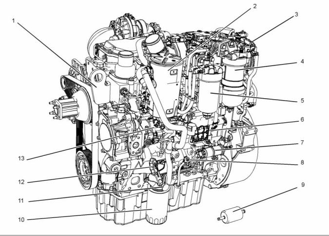
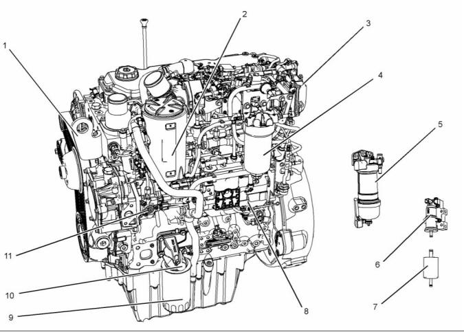
1204E-E44TTA Engine with Series
Turbochargers
g02409511
Illustration 1
Typical example
(1) Front lifting eye
(6) Electronic Control Module (ECM)
(11) Oil sampling valve
(2) Crankcase breather
(3) NOx Reduction System (NRS)
(4) Primary fuel filter
(7) Fuel priming pump
(8) Oil gauge (dipstick)
(9) Fuel strainer
(12) Oil filler
(13) Fuel injection pump
(5) Secondary fuel filter
(10) Oil filter
This document is printed from SPI². Not for RESALE
![]()
![]()
6
Systems Operation Section
KENR9124-01
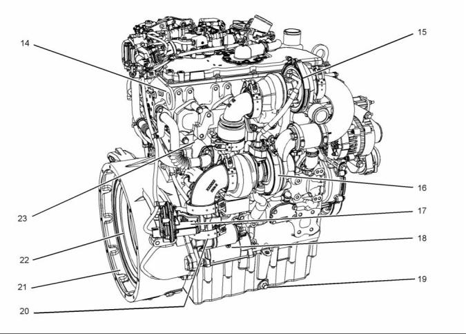
g02409512
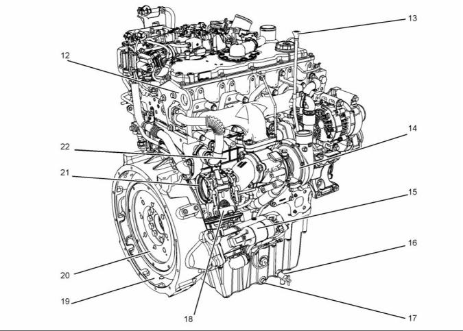
Illustration 2
Typical example
(14) Rear lifting eye
(18) Starting motor
(19) Oil drain plug
(20) Exhaust outlet
(21) Flywheel housing
(22) Flywheel
(23) Exhaust gas cooler (NRS)
(15) High-pressure turbocharger
(16) Low-pressure turbocharger
(17) Back pressure valve
This document is printed from SPI². Not for RESALE
![]()
![]()
KENR9124-01
7
Systems Operation Section
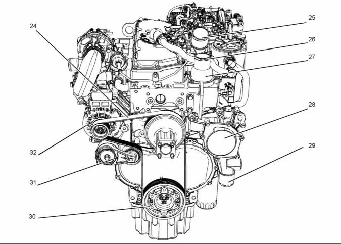
g02409862
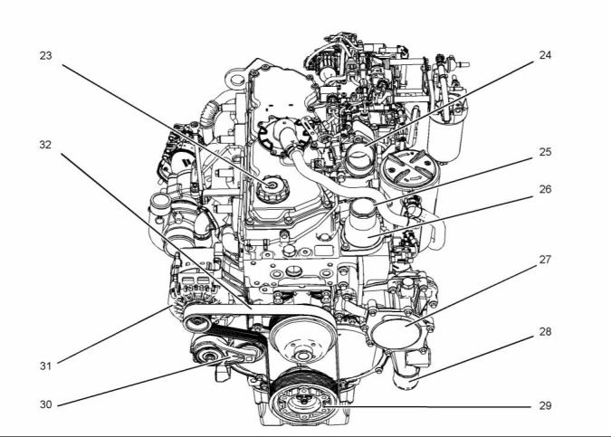
Illustration 3
Typical example
(24) Belt
(25) Connection for air inlet
(26) Coolant outlet connection
(27) Water temperature regulator housing
(28) Water pump
(29) Inlet connection for the coolant
(30) Crankshaft pulley
(31) Belt tensioner
(32) Alternator
This document is printed from SPI². Not for RESALE
![]()
![]()
8
Systems Operation Section
KENR9124-01
1204E-E44TA Engine with Single
Turbocharger
g02407436
Illustration 4
Typical example
(1) Front lifting eye
(5) Primary fuel filter
(9) Oil filter
(2) Crankcase breather
(3) NOx Reduction System (NRS)
(4) Secondary fuel filter
(6) Fuel priming pump
(7) Fuel strainer
(8) Electronic Control Module (ECM)
(10) Oil sampling valve
(11) Fuel injection pump
This document is printed from SPI². Not for RESALE
![]()
![]()
KENR9124-01
9
Systems Operation Section
g02407536
Illustration 5
Typical example
(12) Rear lifting eye
(13) Oil gauge (dipstick)
(14) Turbocharger
(16) Oil drain valve
(17) Oil drain plug
(18) Back pressure valve
(19) Flywheel housing
(20) Flywheel
(21) Exhaust outlet
(22) Exhaust gas cooler (NRS)
(15) Starting motor
This document is printed from SPI². Not for RESALE
![]()
![]()
10
KENR9124-01
Systems Operation Section
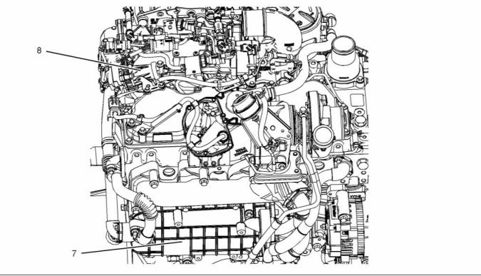
g02407537
Illustration 6
Typical example
(23) Oil filler
(27) Water pump
(31) Alternator
(32) Belt
(24) Connection for air inlet
(25) Outlet connection for the coolant
(26) Water temperature regulator housing
(28) Inlet connection for the coolant
(29) Crankshaft pulley
(30) Belt tensioner
Engine Operation
Basic Engine
Introduction
• Connecting rods
• Crankshaft
i04135810
• Crankshaft pulley
• Timing gear case and gears
• Camshaft
The eight major mechanical components of the basic
engine are the following parts:
• Cylinder block
• Cylinder head
• Pistons
This document is printed from SPI². Not for RESALE
![]()
![]()
KENR9124-01
11
Systems Operation Section
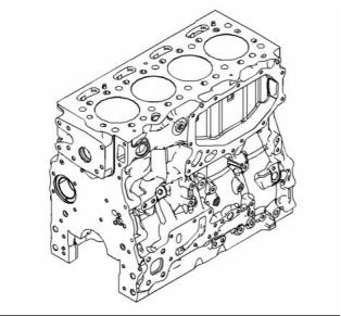
Cylinder Block
Cylinder Head
g02149272
Illustration 7
Typical example
The cast iron cylinder block for the four cylinder
engine has four cylinders which are arranged in-line.
The cylinder block is made of cast iron. The cylinder
block provides support for the full length of the
cylinder bores. The cylinder bores are machined into
the block.
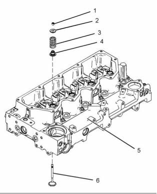
g02466936
Illustration 8
Typical example
(1) Valve keepers
(2) Valve spring retainer
(3) Valve spring
The cylinders are honed to a specially controlled
finish in order to ensure long life and low oil
consumption.
The engine has a cast iron cylinder head (5). The
inlet manifold is integral within the cylinder head.
There are two inlet valves and two exhaust valves for
each cylinder. Each pair of valves (6) are connected
by a valve bridge that is controlled by a pushrod valve
system. The ports for the inlet valves are on the left
side of the cylinder head. The ports for the exhaust
valves are on the right side of the cylinder head. The
valve stems move in valve guides that are pressed
into the cylinder head. There is a renewable stem
seal (4) that fits over the top of the valve guide. The
valve seats are replaceable.
The cylinder block has five main bearings which
support the crankshaft. Thrust washers are installed
on both sides of number 3 main bearing in order to
control the end play of the crankshaft. The thrust
washers can only be installed one way.
Passages supply the lubrication for the crankshaft
bearings. These passages are machined into the
cylinder block.
Cooling passages are cast into the cylinder block in
order to allow the circulation of coolant.
The cylinder block has a bush that is installed for the
front camshaft journal. The other camshaft journals
run directly in the cylinder block.
The engine has a cooling jet that is installed in the
cylinder block for each cylinder. The piston cooling
jet sprays lubricating oil onto the inner surface of the
piston in order to cool the piston.
A Multi-Layered Steel (MLS) cylinder head gasket is
used between the engine block and the cylinder head
in order to seal combustion gases, water, and oil.
This document is printed from SPI². Not for RESALE
![]()
![]()
![]()
12
KENR9124-01
Systems Operation Section
Pistons, Rings, and Connecting
rods
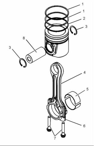
The connecting rods (4) are machined from forged
steel. The connecting rods have bearing caps (6)
that are fracture split. Two connecting rod bearings
(5) are installed between the connecting rod (4) and
the bearing cap (6). The bearing caps on fracture
split connecting rods are retained with Torx bolts (7).
Connecting rods with bearing caps that are fracture
split have the following characteristics:
• The splitting produces an accurately matched
surface on each side of the fracture for improved
strength.
• The correct connecting rod must be installed with
the correct bearing cap. Each connecting rod and
bearing cap have an unique serial number. When a
connecting rod is assembled the serial numbers for
the connecting rod and bearing cap must match.
Crankshaft
g02466938
Illustration 9
Typical example
The pistons (9) have a Quiescent combustion
chamber in the top of the piston in order to provide
an efficient mix of fuel and air. The piston pin (8) is
off-center in order to reduce the noise level. The
position pin (8) is retained in the correct position by
two circlips (3).
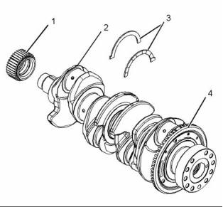
g02155439
Illustration 10
Typical example
(1) Crankshaft gear
(2) Crankshaft
(3) Crankshaft thrust washers
(4) Crankshaft timing ring
The pistons have two compression rings (1) and an
oil control ring (2). The groove for the top ring has
a hard metal insert in order to reduce wear of the
groove. The piston skirt has a low friction coating in
order to reduce the risk of seizure when the engine
is new.
The crankshaft can be a spheroidal graphite iron
casting or a steel forging.
The crankshaft has five main journals. Thrust
washers are installed on both sides of number 3
main bearing in order to control the end play of the
crankshaft.
The correct piston height is important in order to
ensure that the piston does not contact the cylinder
head. The correct piston height also ensures the
efficient combustion of fuel which is necessary in
order to conform to requirements for emissions.
The crankshaft changes the linear energy of the
pistons and connecting rods into rotary torque in
order to power external equipment.
This document is printed from SPI². Not for RESALE
![]()
![]()
![]()
KENR9124-01
13
Systems Operation Section
A gear at the front of the crankshaft drives the timing
gears. The crankshaft gear turns the idler gear which
then turns the following gears:
The camshaft rotates at half the engine speed. The
fuel injection pump rotates at engine speed.
Camshaft
• Camshaft gear
The engine has a single camshaft. The camshaft
is made of cast iron. The camshaft lobes are chill
hardened.
• Fuel injection pump and fuel transfer pump
• The idler gear is driven by the crankshaft gear
which turns the gear of the lubricating oil pump.
The camshaft is driven at the front end. As the
camshaft turns, the camshaft lobes move the valve
system components. The valve system components
move the cylinder valves.
Lip type seals are used on both the front of the
crankshaft and the rear of the crankshaft.
A timing ring is installed to the crankshaft. The timing
ring is used by the ECM in order to measure the
engine speed and the engine position.
The camshaft gear must be timed to the crankshaft
gear. The relationship between the lobes and the
camshaft gear causes the valves in each cylinder to
open at the correct time. The relationship between
the lobes and the camshaft gear also causes the
valves in each cylinder to close at the correct time.
A ring gear for the balancer can be installed to the
crankshaft. When a balancer is installed, the engine
oil pump is an integral part of the balancer assembly.
The ring gear for the balancer drives the balancer.
Gears and Timing Gear Case
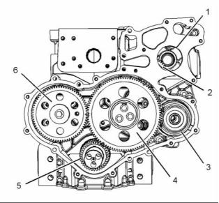
g02212814
Illustration 11
Typical example
(1) Hole for the water pump gear
(3) Position of the accessory drive gear
The crankshaft oil seal is mounted in the cover of
the timing case. The timing case cover is made from
sound-deadened steel or cast iron.
The timing gears are made of steel.
The crankshaft gear (5) drives an upper idler gear
(4) and a lower idler gear. The upper idler gear (4)
drives the camshaft gear (6) and the fuel injection
pump gear (2). The lower idler gear drives the oil
pump. The water pump drive gear is driven by the
fuel injection pump gear.
This document is printed from SPI². Not for RESALE
![]()
![]()
14
KENR9124-01
Systems Operation Section
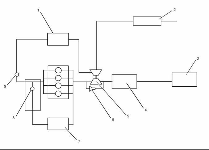
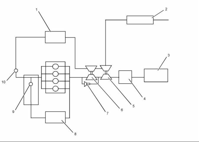
i04302990
Air Inlet and Exhaust System
(Single Turbocharger)
g02469917
Illustration 12
Air inlet and exhaust system
(1) Aftercooler core
(2) Air filter
(3) Diesel particulate filter
(4) Back pressure valve
(5) Turbocharger
(6) Wastegate actuator
(7) Exhaust cooler (NRS)
(8) Exhaust gas valve (NRS)
(9) Wastegate regulator
The components of the air inlet and exhaust system
control the quality of air and the amount of air that is
available for combustion. The air inlet and exhaust
system consists of the following components:
• Cylinder head, injectors, and glow plugs
• Valves and valve system components
• Piston and cylinder
• Air cleaner
• Exhaust manifold
• Exhaust cooler (NRS)
• Exhaust gas valve (NRS)
• Turbocharger
• Diesel oxidation catalyst
• Diesel particulate filter
• Aftercooler
• Inlet manifold
This document is printed from SPI². Not for RESALE
![]()
![]()
KENR9124-01
15
Systems Operation Section
Air is drawn in through the air cleaner into the air inlet
of the turbocharger by the turbocharger compressor
wheel. The air is compressed to a pressure of about
150 kPa (22 psi) and heated to about 120° C (248° F)
before the air is forced to the aftercooler. As the
air flows through the aftercooler the temperature of
the compressed air lowers to about 55° C (131° F).
Cooling of the inlet air assists the combustion
efficiency of the engine. Increased combustion
efficiency helps achieve the following benefits:
• Lower fuel consumption
• Increased power output
• Reduced NOx emission
• Reduced particulate emission
From the aftercooler, the air flows to the exhaust gas
valve (NRS). A mixture of air and exhaust gas is then
forced into the inlet manifold. Air flow from the inlet
manifold to the cylinders is controlled by inlet valves.
There are two inlet valves and two exhaust valves for
each cylinder. The inlet valves open when the piston
moves down on the intake stroke. When the inlet
valves open, cooled compressed air from the inlet
port is forced into the cylinder. The complete cycle
consists of four strokes:
• Inlet
• Compression
• Power
• Exhaust
On the compression stroke, the piston moves back
up the cylinder and the inlet valves close. The cool
compressed air is compressed further. This additional
compression generates more heat.
Note: If the cold starting system is operating, the
glow plugs will also heat the air in the cylinder.
Just before the piston reaches the top center (TC)
position, the ECM operates the electronic unit
injector. Fuel is injected into the cylinder. The air/fuel
mixture ignites. The ignition of the gases initiates the
power stroke. Both the inlet and the exhaust valves
are closed and the expanding gases force the piston
downward toward the bottom center (BC) position.
From the BC position, the piston moves upward.
This initiates the exhaust stroke. The exhaust valves
open. The exhaust gases are forced through the
open exhaust valves into the exhaust manifold.
This document is printed from SPI². Not for RESALE
![]()
16
KENR9124-01
Systems Operation Section
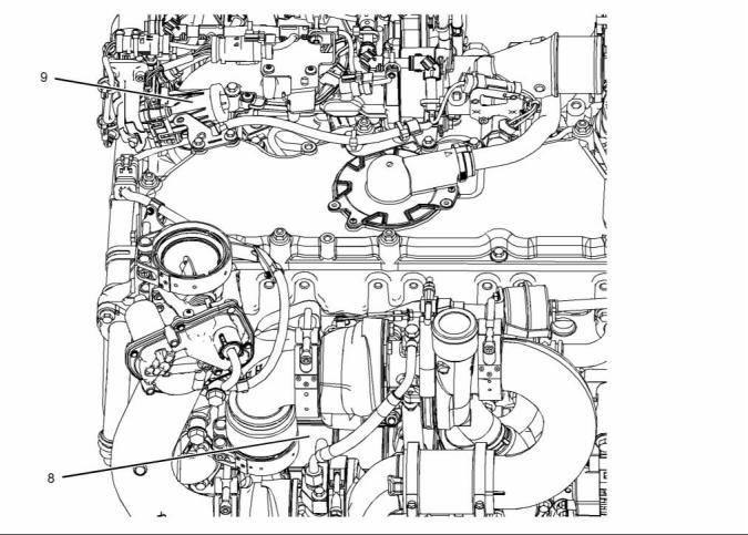
g02469919
Illustration 13
Typical example
The NOx Reduction System (NRS) operates with
the transfer of the hot exhaust gas from the exhaust
manifold to the exhaust cooler (7). The hot exhaust
gas is cooled in the exhaust cooler. The now cooled
exhaust gas passes through the assembly of exhaust
gas valve.
Exhaust gases from the exhaust manifold enter
the inlet of the turbocharger in order to turn the
turbocharger turbine wheel. The turbine wheel is
connected to a shaft that rotates. The exhaust gases
pass from the turbocharger through the following
components: exhaust outlet, back pressure valve,
Diesel Oxidation Catalyst (DOC), Diesel Particulate
Filter (DPF), and exhaust pipe.
The reed valves that are located in the exhaust gas
valve (NRS) has one main function. The one main
function is to prevent the reverse flow of charge air
from the inlet side of the engine to the exhaust side
of the engine.
As the electronically controlled valve (8) starts to
open the flow of cooled exhaust gas from the exhaust
cooler (7) mixes with the air flow from the charge air
aftercooler. The mixing of the cooled exhaust gas and
the air flow from the charge air aftercooler reduces
the oxygen content of the gas mixture. This results in
a lower combustion temperature, so decreases the
production of NOx.
As the demand for more cooled exhaust gas
increases the electronically controlled valve opens
further. The further opening of the valve increases
the flow of cooled exhaust gas from the exhaust
cooler. As the demand for cooled exhaust gas
decreases, the electronically controlled valve closes.
This decreases the flow of cooled exhaust gas from
the exhaust cooler.
This document is printed from SPI². Not for RESALE
![]()
![]()
KENR9124-01
17
Systems Operation Section
Turbocharger
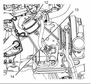
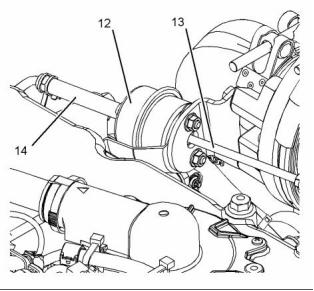
g02469997
Illustration 15
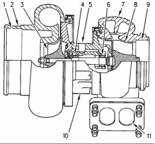
g00302786
Illustration 14
Typical example
(12) Wastegate actuator
(13) Actuating lever
(14) Line (boost pressure)
Typical example of a cross section of a turbocharger
(1) Air intake
(2) Compressor housing
(3) Compressor wheel
(4) Bearing
(5) Oil inlet port
(6) Bearing
(7) Turbine housing
(8) Turbine wheel
(9) Exhaust outlet
(10) Oil outlet port
(11) Exhaust inlet
The turbocharger is mounted on the outlet of the
exhaust manifold. The exhaust gas from the exhaust
manifold enters the exhaust inlet (11) and passes
through the turbine housing (7) of the turbocharger.
Energy from the exhaust gas causes the turbine
wheel (8) to rotate. The turbine wheel is connected
by a shaft to the compressor wheel (3).
As the turbine wheel rotates, the compressor wheel
is rotated. The rotation of the compressor wheel
causes the intake air to be pressurized through the
compressor housing (2) of the turbocharger.
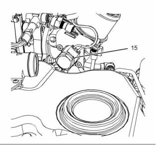
g02151895
Illustration 16
Typical example
(15) Wastegate regulator
When the load on the engine increases, more fuel
is injected into the cylinders. The combustion of
this additional fuel produces more exhaust gases.
The additional exhaust gases cause the turbine and
the compressor wheels of the turbocharger to turn
faster. As the compressor wheel turns faster, air is
compressed to a higher pressure and more air is
forced into the cylinders. The increased flow of air
into the cylinders allows the fuel to be burnt with
greater efficiency. This produces more power.
This document is printed from SPI². Not for RESALE
![]()
![]()

![]()
![]()
18
KENR9124-01
Systems Operation Section
Crankcase Breather
A wastegate is installed on the turbine housing of
the turbocharger. The wastegate is a valve that
allows exhaust gas to bypass the turbine wheel of
the turbocharger. The operation of the wastegate is
dependent on the pressurized air (boost pressure)
from the turbocharger compressor. The boost
pressure acts on a diaphragm that is spring loaded
in the wastegate actuator which varies the amount of
exhaust gas that flows into the turbine.
The engine crankcase breather is a filtered system.
The crankcase breather system consists of two
main elements, a primary separator in the valve
mechanism cover and a filtered canister that is
mounted on the cylinder head. The gases exit the
engine through the valve mechanism cover. The
gases then pass through the primary separator. The
primary separator removes most of the liquid oil from
the gas. The liquid oil is then returned to the engine.
The wastegate regulator (15) is controlled by the
engine Electronic Control Module (ECM). The
ECM uses inputs from a number of engine sensors
to determine the optimum boost pressure. This
will achieve the best exhaust emissions and fuel
consumption at any given engine operating condition.
The ECM controls the wastegate regulator, that
regulates the boost pressure to the wastegate
actuator.
The gas then passes through the filter element before
exiting to atmosphere in an open breather system
or back to the induction system in a closed breather
system via the breather vent pipe.
Any liquid oil that is captured by the filter drains from
the bottom of the canister. The liquid oil is returned
by the drain pipe that runs from the bottom of the
canister back to the crankcase. A valve connects the
drain pipe to the crankcase. This valve prevents the
bypass of gas past the filter and oil from passing up
the drain pipe.
When higher boost pressure is needed for the
engine performance, a signal is sent from the ECM
to the wastegate regulator. The wastegate regulator
reduces the pressure in the air inlet pipe (14) that
acts upon the diaphragm within the wastegate
actuator (12).
A pressure relief valve is located in the rear of the
canister in the integral mounting bracket. Under
normal operation of the engine, this valve will not
operate. If part of the system becomes blocked the
valve will open at a pressure of 8.5 kPa (1.2 psi). The
open valve will allow gas to bypass the filter and the
pipes for venting.
The spring within the wastegate actuator (12) forces
the wastegate valve that is within the turbine housing
to close via the actuating rod and lever. When the
wastegate valve is closed, more exhaust gas is able
to pass over the turbine wheel. This results in an
increase in turbocharger speed and boost pressure
generation.
The filter element can be accessed by removing
the top cap of the canister. Refer to Operation and
Maintenance Manual, “Engine Crankcase Breather
Element - Replace” for the correct procedure.
When lower boost pressure is needed for the engine
performance, a signal is sent from the ECM to the
wastegate regulator. This causes high pressure in
the air inlet pipe (14) to act on the diaphragm within
the wastegate actuator (12). The actuating rod (13)
acts upon the actuating lever to open the valve in
the wastegate. When the valve in the wastegate is
opened, more exhaust gas from the engine is able to
bypass the turbine wheel. The exhaust gases bypass
the turbine wheel results in a decrease in the speed
of the turbocharger.
NOTICE
The crankcase breather gases are part of the engines
measured emissions output. Any tampering with the
breather system could invalidate the engines emis-
sions compliance.
The shaft that connects the turbine to the compressor
wheel rotates in bearings (4) and (6). The bearings
require oil under pressure for lubrication and cooling.
The oil that flows to the lubricating oil inlet port (5)
passes through the center of the turbocharger which
retains the bearings. The oil exits the turbocharger
from the lubricating oil outlet port (10) and returns
to the oil pan.
This document is printed from SPI². Not for RESALE
![]()
![]()
![]()
KENR9124-01
19
Systems Operation Section
Valve System Components
The engine lubricating oil enters the lifter (4) through
a non-return valve. The engine lubricating oil
increases the length of the lifter (4) until all valve lash
is removed. If the engine is stationary for a prolonged
period the valve springs will cause the lifter (4) to
shorten so that when the engine is started engine
valve lash is present for the first few seconds.
After cranking restores oil pressure the lifter (4)
increases in length and removes the valve lash.
When load is removed from a lifter (4) during service
work by the removal of the rocker shaft the lifter
(4) increases in length to the maximum extent.
Refer to Systems Operation, Testing and Adjusting,
“Position the Valve Mechanism Before Maintenance
Procedures” for the correct procedure.
During reassembly of the rocker shaft the engine
must be put into a safe position to avoid engine
damage. After load is imposed on the lifters by
reassembling the rocker assembly, the engine must
be left in safe position for a safe period until the
lifters have reduced to the correct length. Refer to
Disassembly and Assembly, “Rocker Shaft and
Pushrod - Install” for the correct procedure.
Upward movement of the pushrod against rocker arm
(2) results in a downward movement that acts on the
valve bridge (1). This action opens a pair of valves (7)
which compresses the valve springs (6). When the
camshaft (5) has rotated to the peak of the lobe, the
valves are fully open. When the camshaft (5) rotates
further, the two valve springs (6) under compression
start to expand. The valve stems are under tension of
the springs. The stems are pushed upward in order
to maintain contact with the valve bridge (1). The
continued rotation of the camshaft causes the rocker
arm (2), the pushrods (3) and the lifters (4) to move
downward until the lifter reaches the bottom of the
lobe. The valves (7) are now closed. The cycle is
repeated for all the valves on each cylinder.
g01924293
Illustration 17
Valve system components
(1) Bridge
(2) Rocker arm
(3) Pushrod
(4) Lifter
(5) Camshaft
(6) Spring
(7) Valve
The valve system components control the flow of
inlet air into the cylinders during engine operation.
The valve system components also control the flow
of exhaust gases out of the cylinders during engine
operation.
The crankshaft gear drives the camshaft gear through
an idler gear. The camshaft (5) must be timed to the
crankshaft in order to get the correct relation between
the piston movement and the valve movement.
The camshaft (5) has two camshaft lobes for each
cylinder. The lobes operate either a pair of inlet
valves or a pair of exhaust valves. As the camshaft
turns, lobes on the camshaft cause the lifter (4) to
move the pushrod (3) up and down.
The lifter (4) incorporates a hydraulic lash adjuster
which removes valve lash from the valve mechanism.
The lifter (4) uses engine lubricating oil to compensate
for wear of system components so that no service
adjustment of valve lash is needed.
This document is printed from SPI². Not for RESALE
![]()
![]()

20
KENR9124-01
Systems Operation Section
i04302992
Air Inlet and Exhaust System
(Series Turbochargers)
g02467317
Illustration 18
Air inlet and exhaust system
(1) Aftercooler core
(2) Air filter
(3) Diesel particulate filter
(4) Back pressure valve
(5) Low-pressure turbocharger
(6) High-pressure turbocharger
(7) Wastegate actuator
(9) Exhaust gas valve (NRS)
(10) Wastegate regulator
(8) Exhaust cooler (NRS)
The components of the air inlet and exhaust system
control the quality of air and the amount of air that is
available for combustion. The air inlet and exhaust
system consists of the following components:
• Inlet manifold
• Cylinder head, injectors, and glow plugs
• Valves and valve system components
• Piston and cylinder
• Air cleaner
• Exhaust cooler (NRS)
• Exhaust gas valve (NRS)
• Turbochargers
• Exhaust manifold
• Diesel oxidation catalyst
• Diesel particulate filter
• Aftercooler
This document is printed from SPI². Not for RESALE
![]()
![]()
KENR9124-01
21
Systems Operation Section
Air is drawn in through the air cleaner into the
air inlet of the low-pressure turbochar, ger by the
low-pressure turbocharger compressor wheel. The
air is compressed to a pressure of about 75 kPa
(11 psi) and heated to about 120° C (248° F). From
the low-pressure turbocharger, the air passes to the
high-pressure turbocharger. The air is compressed
to a pressure of about 220 kPa (32 psi) and heated
to about 240° C (464° F) before the air is forced to
the aftercooler. The air flows through the aftercooler.
The temperature of the compressed air lowers to
about 55° C (131° F). Cooling of the inlet air assists
the combustion efficiency of the engine. Increased
combustion efficiency helps achieve the following
benefits:
From the BC position, the piston moves upward. The
piston moving upward initiates the exhaust stroke.
The exhaust valves open. The exhaust gases are
forced through the open exhaust valves into the
exhaust manifold.
• Lower fuel consumption
• Increased power output
• Reduced NOx emission
• Reduced particulate emission
From the aftercooler, the air flows to the exhaust gas
valve (NRS). A mixture of air and exhaust gas is then
forced into the inlet manifold. Air flow from the inlet
manifold to the cylinders is controlled by inlet valves.
There are two inlet valves and two exhaust valves for
each cylinder. The inlet valves open when the piston
moves down on the intake stroke. When the inlet
valves open, cooled compressed air from the inlet
port is forced into the cylinder. The complete cycle
consists of four strokes:
• Inlet
• Compression
• Power
• Exhaust
On the compression stroke, the piston moves back
up the cylinder and the inlet valves close. The cool
compressed air is compressed further. This additional
compression generates more heat.
Note: If the cold starting system is operating, the
glow plugs will also heat the air in the cylinder.
Just before the piston reaches the top center (TC)
position, the ECM operates the electronic unit
injector. Fuel is injected into the cylinder. The air/fuel
mixture ignites. The ignition of the gases initiates the
power stroke. Both the inlet and the exhaust valves
are closed and the expanding gases force the piston
downward toward the bottom center (BC) position.
This document is printed from SPI². Not for RESALE
![]()
22
KENR9124-01
Systems Operation Section
g02467360
Illustration 19
Typical example
The NOx Reduction System (NRS) operates with
the transfer of the hot exhaust gas from the exhaust
manifold to the exhaust cooler (8). The hot exhaust
gas is cooled in the exhaust cooler (8). The now
cooled exhaust gas passes through the assembly
of the exhaust gas valve.
As the demand for more cooled exhaust gas
increases the electronically controlled valve opens
further. The further opening of the valve increases
the flow of cooled exhaust gas from the exhaust
cooler. As the demand for cooled exhaust gas
decreases, the electronically controlled valve closes.
This decreases the flow of cooled exhaust gas from
the exhaust cooler.
The reed valves that are located in the exhaust gas
valve (NRS) has one main function. The one main
function is to prevent the reverse flow of charge air
from the inlet side of the engine to the exhaust side
of the engine.
Exhaust gases from the exhaust manifold enter the
inlet of the high-pressure turbocharger in order to turn
the high-pressure turbocharger turbine wheel. The
turbine wheel is connected to a shaft that rotates.
The exhaust gases travel from the high-pressure
turbocharger. The exhaust gases then travel through
the duct on the turbine side into the turbine inlet of
the low-pressure turbocharger in order to power
the low-pressure turbocharger. The exhaust gases
pass from the low-pressure turbocharger through the
following components: exhaust outlet, back pressure
valve, Diesel Oxidation Catalyst (DOC), Diesel
Particulate Filter (DPF), and exhaust pipe.
As the electronically controlled valve (9) starts to
open the flow of cooled exhaust gas from the exhaust
cooler (8) mixes with the air flow from the charge air
aftercooler. The mixing of the cooled exhaust gas and
the air flow from the charge air aftercooler reduces
the oxygen content of the gas mixture. This results in
a lower combustion temperature, so decreases the
production of NOx.
This document is printed from SPI². Not for RESALE
![]()
![]()
KENR9124-01
23
Systems Operation Section
Turbochargers
g02467380
Illustration 21
g00302786
Illustration 20
Typical example
(12) Wastegate actuator
(13) Actuating lever
(14) Line (boost pressure)
Typical example of a cross section of a turbocharger
(1) Air intake
(2) Compressor housing
(3) Compressor wheel
(4) Bearing
(5) Oil inlet port
(6) Bearing
(7) Turbine housing
(8) Turbine wheel
(9) Exhaust outlet
(10) Oil outlet port
(11) Exhaust inlet
The high-pressure turbocharger is mounted on the
outlet of the exhaust manifold. The low-pressure
turbocharger is mounted on the side of the cylinder
block. The exhaust gas from the exhaust manifold
enters the exhaust inlet (11) and passes through
the turbine housing (7) of the turbocharger. Energy
from the exhaust gas causes the turbine wheel (8) to
rotate. The turbine wheel is connected by a shaft to
the compressor wheel (3).
As the turbine wheel rotates, the compressor
wheel is rotated. This causes the intake air to be
pressurized through the compressor housing (2) of
the turbocharger.
g02151895
Illustration 22
Typical example
(15) Wastegate regulator
When the load on the engine increases, more fuel
is injected into the cylinders. The combustion of
this additional fuel produces more exhaust gases.
The additional exhaust gases cause the turbine and
the compressor wheels of the turbocharger to turn
faster. As the compressor wheel turns faster, air is
compressed to a higher pressure and more air is
forced into the cylinders. The increased flow of air
into the cylinders allows the fuel to be burnt with
greater efficiency. This produces more power.
This document is printed from SPI². Not for RESALE
![]()
![]()
![]()
![]()

24
KENR9124-01
Systems Operation Section
Crankcase Breather
A wastegate is installed on the compressor side
of the turbocharger. The wastegate is a valve that
allows exhaust gas to bypass the turbine wheel of
the turbocharger. The operation of the wastegate is
dependent on the pressurized air (boost pressure)
from the turbocharger compressor. The boost
pressure acts on a diaphragm that is spring loaded
in the wastegate actuator which varies the amount of
exhaust gas that flows into the turbine.
The engine crankcase breather is a filtered system.
The crankcase breather system consists of two
main elements, a primary separator in the valve
mechanism cover and a filtered canister that is
mounted on the cylinder head. The gases exit the
engine through the valve mechanism cover. The
gases then pass through the primary separator. The
primary separator removes most of the liquid oil from
the gas. The liquid oil is then returned to the engine.
The wastegate regulator (15) is controlled by the
engine Electronic Control Module (ECM). The
ECM uses inputs from a number of engine sensors
to determine the optimum boost pressure. This
will achieve the best exhaust emissions and fuel
consumption at any given engine operating condition.
The ECM controls the wastegate regulator, that
regulates the boost pressure to the wastegate
actuator.
The gas then passes through the filter element before
exiting to atmosphere in an open breather system
or back to the induction system in a closed breather
system via the breather vent pipe.
Any liquid oil that is captured by the filter drains from
the bottom of the canister. The liquid oil is returned
by the drain pipe that runs from the bottom of the
canister back to the crankcase. A valve connects the
drain pipe to the crankcase. This valve prevents the
bypass of gas past the filter and oil from passing up
the drain pipe.
When higher boost pressure is needed for the
engine performance, a signal is sent from the ECM
to the wastegate regulator. The wastegate regulator
reduces the pressure in the air inlet pipe (14) that
acts upon the diaphragm within the wastegate
actuator (13).
A pressure control valve is located in the top cap
of the canister. This valve regulates the crankcase
pressure on the closed breather system.
The spring within the wastegate actuator (13) forces
the wastegate valve that is within the turbine housing
to close via the actuating rod and lever. When the
wastegate valve is closed, more exhaust gas is able
to pass over the turbine wheel. This results in an
increase in turbocharger speed and boost pressure
generation.
A pressure relief valve is located in the rear of the
canister in the integral mounting bracket. Under
normal operation of the engine, this valve will not
operate. If part of the system becomes blocked the
valve will open at a pressure of 8.5 kPa (1.2 psi). The
open valve will allow gas to bypass the filter and the
pipes for venting.
When lower boost pressure is needed for the engine
performance, a signal is sent from the ECM to the
wastegate regulator. This causes high pressure in
the air inlet pipe (14) to act on the diaphragm within
the wastegate actuator (13). The actuating rod (12)
acts upon the actuating lever to open the valve in
the wastegate. When the valve in the wastegate is
opened, more exhaust gas from the engine is able to
bypass the turbine wheel. The exhaust gases bypass
the turbine wheel results in a decrease in the speed
of the turbocharger.
The filter element can be accessed by removing
the top cap of the canister. Refer to Operation and
Maintenance Manual, “Engine Crankcase Breather
Element - Replace” for the correct procedure.
NOTICE
The crankcase breather gases are part of the engines
measured emissions output. Any tampering with the
breather system could invalidate the engines emis-
sions compliance.
The shaft that connects the turbine to the compressor
wheel rotates in bearings (4) and (6). The bearings
require oil under pressure for lubrication and cooling.
The oil that flows to the lubricating oil inlet port (5)
passes through the center of the turbocharger which
retains the bearings. The oil exits the turbocharger
from the lubricating oil outlet port (10) and returns
to the oil pan.
This document is printed from SPI². Not for RESALE
![]()
![]()
![]()
KENR9124-01
25
Systems Operation Section
Valve System Components
The engine lubricating oil enters the lifter (4) through
a non-return valve. The engine lubricating oil
increases the length of the lifter (4) until all valve lash
is removed. If the engine is stationary for a prolonged
period the valve springs will cause the lifter (4) to
shorten so that when the engine is started engine
valve lash is present for the first few seconds.
After cranking restores oil pressure the lifter (4)
increases in length and removes the valve lash.
When load is removed from a lifter (4) during service
work by the removal of the rocker shaft the lifter
(4) increases in length to the maximum extent.
Refer to Systems Operation, Testing and Adjusting,
“Position the Valve Mechanism Before Maintenance
Procedures” for the correct procedure.
During reassembly of the rocker shaft the engine
must be put into a safe position to avoid engine
damage. After load is imposed on the lifters by
reassembling the rocker assembly, the engine must
be left in safe position for a safe period until the
lifters have reduced to the correct length. Refer to
Disassembly and Assembly, “Rocker Shaft and
Pushrod - Install” for the correct procedure.
Upward movement of the pushrod against rocker arm
(2) results in a downward movement that acts on the
valve bridge (1). This action opens a pair of valves (7)
which compresses the valve springs (6). When the
camshaft (5) has rotated to the peak of the lobe, the
valves are fully open. When the camshaft (5) rotates
further, the two valve springs (6) under compression
start to expand. The valve stems are under tension of
the springs. The stems are pushed upward in order
to maintain contact with the valve bridge (1). The
continued rotation of the camshaft causes the rocker
arm (2), the pushrods (3) and the lifters (4) to move
downward until the lifter reaches the bottom of the
lobe. The valves (7) are now closed. The cycle is
repeated for all the valves on each cylinder.
g01924293
Illustration 23
Valve system components
(1) Bridge
(2) Rocker arm
(3) Pushrod
(4) Lifter
(5) Camshaft
(6) Spring
(7) Valve
The valve system components control the flow of
inlet air into the cylinders during engine operation.
The valve system components also control the flow
of exhaust gases out of the cylinders during engine
operation.
i04332330
Clean Emissions Module
The crankshaft gear drives the camshaft gear through
an idler gear. The camshaft (5) must be timed to the
crankshaft in order to get the correct relation between
the piston movement and the valve movement.
To meet current emissions legislation requirements,
a small amount of certain chemical compounds that
are emitted by the engine must not be allowed to
enter the atmosphere. The Clean Emissions Module
(CEM) that is installed to the engine is designed to
convert these chemical compounds into less harmful
compounds.
The camshaft (5) has two camshaft lobes for each
cylinder. The lobes operate either a pair of inlet
valves or a pair of exhaust valves. As the camshaft
turns, lobes on the camshaft cause the lifter (4) to
move the pushrod (3) up and down.
The lifter (4) incorporates a hydraulic lash adjuster
which removes valve lash from the valve mechanism.
The lifter (4) uses engine lubricating oil to compensate
for wear of system components so that no service
adjustment of valve lash is needed.
This document is printed from SPI². Not for RESALE
![]()
![]()
26
KENR9124-01
Systems Operation Section
g02384560
Illustration 24
Typical example
(1) Clean emissions module (CEM)
(2) Inlet connection
(3) Outlet connection
(4) Mounting cradle
(5) Flexible exhaust pipe from engine to
CEM
The Clean Emissions Module (CEM) for the engine
consists of the following components.
The rate of accumulation of ash is slow under normal
engine operating conditions. The filter is designed
to contain all the ash that is produced for the life of
the engine.
• Diesel Oxidation Catalyst (DOC)
• Diesel Particulate Filter (DPF)
The engine aftertreatment system is designed to
oxidize the soot in the DPF at the same rate as the
soot is produced by the engine. The oxidization of
the soot will occur when the engine is operating
under normal conditions. The soot in the DPF is
constantly monitored. If the engine is operated in a
way that produces more soot than the oxidized soot,
the engine management system will automatically
activate systems to raise the exhaust temperature.
The raising of the exhaust temperature will ensure
that more soot is oxidized than the soot that is
produced by the engine. The oxidization of more
soot returns the DPF to a reduced level of soot. The
systems are then deactivated when the soot level
has been reduced.
The Diesel Oxidation Catalyst (DOC) oxidizes the
carbon monoxide and the hydrocarbons that are
not burnt in the exhaust gas into carbon dioxide
and water. The Diesel Oxidation Catalyst (DOC) is
a through flow device that will continue to operate
during all normal engine operating conditions.
The Diesel Particulate Filter (DPF) collects all
particulate matter in the exhaust gas.
A flexible exhaust pipe connects the engine to
the Clean Emissions Module (CEM). Refer to
Disassembly and Assembly for the correct procedure
to install the flexible exhaust pipe.
The engine ECM must know how much soot is in the
DPF. Measurement of soot is accomplished through
the following means:
The solid particulate matter that is collected by the
DPF consists of soot (carbon) from incomplete
combustion of the fuel and inorganic ash from the
combustion of any oil in the cylinder.
• Radio frequency measurement across the DPF
• Calculated model based on developed engine out
soot measurements
This document is printed from SPI². Not for RESALE
![]()
![]()

KENR9124-01
27
Systems Operation Section
The Electronic Control Module (ECM) uses the soot
measurement information to determine if the engine
operating conditions need to be adjusted in order to
oxidize the soot at an increased rate.
If a replacement Diesel Particulate Filter (DPF) is
required, contact your Perkins distributor.
i04135351
Cooling System
Introduction
The cooling system has the following components:
• Radiator
• Water pump
• Cylinder block
• Oil cooler
• Exhaust gas cooler (NRS)
• Cylinder head
• Water temperature regulator
This document is printed from SPI². Not for RESALE
![]()
28
KENR9124-01
Systems Operation Section
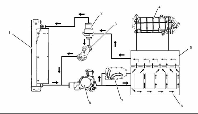
Coolant Flow
g02332698
Illustration 25
Typical example
(1) Radiator
(4) Exhaust gas cooler (NRS)
(5) Cylinder head
(6) Cylinder block
(8) Water pump
(2) Water temperature regulator and housing
(3) Bypass for the water temperature
regulator
(7) Engine oil cooler
The coolant flows from the bottom of the radiator (1)
to the centrifugal water pump (8). The water pump
(8) is installed on the front of the timing case. The
water pump (8) is driven by a gear. The gear of the
fuel injection pump drives the water pump gear.
Some coolant flows through a cavity in the front of
the cylinder head (5). Some coolant is diverted into
the exhaust gas cooler (4) by a coolant pipe in the
rear of the cylinder head (5). The coolant then flows
out of the exhaust gas cooler (4) to the cavity in the
cylinder head (5).
The water pump (8) contains a rotary seal that uses
the engine coolant as a lubricating medium. This will
ensure that an adequate sealing film is created. The
sealing film is maintained in order to reduce heat
generation. Heat that is generated by the rotating
sealing faces under normal operating conditions
causes a small flow of coolant to be emitted into a
chamber. The water pump (8) pumps the coolant
through a passage in the timing case to the front of
the cylinder block (6).
The coolant then flows into the housing of the water
temperature regulator (2). If the water temperature
regulator (2) is closed, the coolant goes directly
through a bypass (3) to the inlet side of the water
pump. If the water temperature regulator is open, and
the bypass is closed then the coolant flows to the top
of the radiator (1).
The coolant enters a passage in the left side of the
cylinder block (6). Some coolant enters the cylinder
block. Some coolant passes over the element of the
oil cooler (7). The coolant then enters the block (6).
Coolant flows around the outside of the cylinders
then flows from the cylinder block into the cylinder
head (5).
This document is printed from SPI². Not for RESALE
![]()
![]()
KENR9124-01
29
Systems Operation Section
The hub of the idler gear is lubricated by oil from the
oil gallery. The timing gears are lubricated by the
splash from the oil.
i03909669
Lubrication System
An external line supplies oil to the high-pressure fuel
pump. The oil then flows through a return line into the
timing case and back to the oil pan.
Lubricating oil from the oil pan flows through a
strainer and a pipe to the suction side of the engine
oil pump. Pressure for the lubrication system is
supplied by the oil pump. The crankshaft gear drives
a lower idler gear. The lower idler gear drives the oil
pump gear. The pump has an inner rotor and an outer
rotor. The axis of rotation of the rotors are off-center
relative to each other. There is an interference fit
between the inner rotor and the drive shaft.
Engines have piston cooling jets that are supplied
with oil from the oil gallery. The piston cooling jets
spray lubricating oil on the underside of the pistons in
order to cool the pistons.
i03922889
Electrical System
If a balancer is installed, the engine oil pressure
is provided by an integrated engine oil pump. The
integrated engine oil pump is located in the balancer.
The electrical system is a negative ground system.
The inner rotor has five lobes which mesh with the six
lobes of the outer rotor. When the pump rotates, the
distance increases between the lobes of the outer
rotor and the lobes of the inner rotor in order to create
suction. When the distance decreases between the
lobes, pressure is created.
The charging circuit operates when the engine
is running. The alternator in the charging circuit
produces direct current for the electrical system.
Starting Motor
The lubricating oil flows from the outlet side of the oil
pump through a passage to the oil filter head. The oil
then flows from the oil filter head through a passage
to a plate type oil cooler. The oil cooler is located on
the left side of the cylinder block.
From the oil cooler, the oil returns through a passage
to the oil filter head. The oil then flows through a
bypass valve that permits the lubrication system
to function if the oil filter becomes blocked. Under
normal conditions, the oil then flows to the oil filter.
The oil flows from the oil filter through a passage that
is drilled across the cylinder block to the oil gallery.
The oil gallery is drilled through the total length of
the left side of the cylinder block. If the oil filter is on
the right side of the engine, the oil flows through a
passage that is drilled across the cylinder block to
the pressure gallery.
Lubricating oil from the oil gallery flows through
high-pressure passages to the main bearings of the
crankshaft. Then, the oil flows through the passages
in the crankshaft to the connecting rod bearing
journals. The pistons and the cylinder bores are
lubricated by the splash of oil and the oil mist.
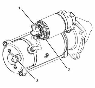
g01964824
Illustration 26
Typical example
12 V 4 kW Starting Motor
(1) Terminal 30 for connection of the battery cable
(2) Terminal 50 for connection of ignition switch
(3) Terminal 31 for connection of the ground
Lubricating oil from the main bearings flows through
passages in the cylinder block to the journals of the
camshaft. Then, the oil flows from the front journal of
the camshaft at a reduced pressure to the cylinder
head. The oil then flows through the center of the
rocker shaft to the rocker arm levers. The valve
stems, the valve springs and the valve lifters are
lubricated by the splash and the oil mist.
This document is printed from SPI². Not for RESALE
![]()
![]()
30
KENR9124-01
Systems Operation Section
Certain higher powered starting motors are designed
with an Integrated Magnetic Switch (IMS). The
Integrated Magnetic Switch (IMS) is activated by the
ignition switch. The solenoid circuit then engages the
starting motor. The benefit of Integrated Magnetic
Switch (IMS) is a lower current in the ignition circuit
that will allow the engine ECM to control ignition
without the use of a relay.
Alternator
The electrical outputs of the alternator have the
following characteristics:
• Three-phase
• Full-wave
• Rectified
The alternator is an electro-mechanical component.
The alternator is driven by a belt from the crankshaft
pulley. The alternator charges the storage battery
during the engine operation.
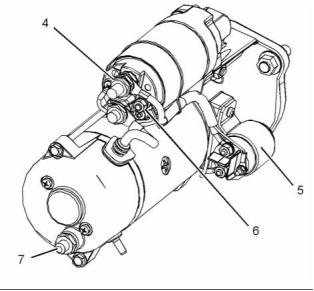
g01964833
Illustration 27
Typical example
24 V 5.5 kW Starting Motor
(4) Terminal 30 for connection of the battery cable
(5) Integrated Magnetic Switch (IMS)
(6) Terminal 50 for connection of ignition switch
(7) Terminal 31 for connection of the ground
The alternator is cooled by an external fan which is
mounted behind the pulley. The fan may be mounted
internally. The fan forces air through the holes in the
front of the alternator. The air exits through the holes
in the back of the alternator.
The starting motor turns the engine via a gear on the
engine flywheel. The starting motor speed must be
high enough in order to initiate a sustained operation
of the fuel ignition in the cylinders.
The alternator converts the mechanical energy and
the magnetic field into alternating current and voltage.
This conversion is done by rotating a direct current
electromagnetic field on the inside of a three-phase
stator. The electromagnetic field is generated by
electrical current flowing through a rotor. The stator
generates alternating current and voltage.
The starting motor consists of the main armature and
a solenoid. The solenoid is a relay with two windings
Pull-In (PI) and Hold-In (HI). Upon activation of
ignition switch, both windings move the iron core
by electromagnets. The linkage from the iron core
acts to move the pinion toward the flywheel ring
gear for engagement. Upon complete engagement,
the solenoid completes the high current circuit that
supplies electric power to the main armature in order
to provide rotation. During cranking of the engine,
only the Hold-In (HI) winding is active.
The alternating current is changed to direct current
by a three-phase, full-wave rectifier. Direct current
flows to the output terminal of the alternator. The
direct current is used for the charging process.
A regulator is installed on the rear end of the
alternator. Two brushes conduct current through two
slip rings. The current then flows to the rotor field. A
capacitor protects the rectifier from high voltages.
The ignition switch is deactivated once the desired
engine speed has been achieved. The circuit is
disconnected. The armature will stop rotating. Return
springs that are located on the shafts and the
solenoid will disengage the pinion from flywheel ring
gear back to the rest position.
The alternator is connected to the battery for charging
and machine load requirements. A warning lamp can
be connected via the ignition switch. This wiring is
optional.
The armature of the starting motor and the
mechanical transmissions may be damaged if the
increases in the speed of the engine are greater
than the pinion of the starting motor. Damage may
occur when the engine is started or after the engine
is started. An overrunning clutch prevents damage to
the armature of the starting motor and mechanical
transmissions.
This document is printed from SPI². Not for RESALE
![]()
![]()
KENR9124-01
31
Systems Operation Section
Refueling
i04103311
Cleanliness of Fuel System
Components
In order to refuel the diesel fuel tank, the refueling
pump and the fuel tank cap assembly must be clean
and free from dirt and debris. Refueling should take
place only when the ambient conditions are free from
dust, wind, and rain.
Cleanliness of the Engine
Only use fuel that is free from contamination. Ultra
Low Sulfur Diesel (ULSD) must be used. The content
of sulfur in Ultra Low Sulfur Diesel (ULSD) fuel must
be below 15 PPM 0.0015%.
NOTICE
It is important to maintain extreme cleanliness when
working on the fuel system, since even tiny particles
can cause engine or fuel system problems.
Biodiesel may be used. The neat biodiesel must
conform to the latest “EN14214 or ASTM D6751”
(in the USA). The biodiesel can only be blended in
mixture of up to 20% by volume in acceptable mineral
diesel fuel meeting latest edition of “EN590 or ASTM
D975 S15” designation.
The entire engine should be washed with a
high-pressure water system. Washing the engine will
remove dirt and loose debris before a repair on the
fuel system is started. Ensure that no high-pressure
water is directed at the seals for the injectors.
In United States, Biodiesel blends of B6 to B20 must
meet the requirements listed in the latest edition of
“ASTM D7467” (B6 to B20) and must be of an API
gravity of 30-45.
Environment
When possible, the service area should be positively
pressurized. Ensure that the components are not
exposed to contamination from airborne dirt and
debris. When a component is removed from the
system, the exposed fuel connections must be
closed off immediately with suitable sealing plugs.
The sealing plugs should only be removed when
the component is reconnected. The sealing plugs
must not be reused. Dispose of the sealing plugs
immediately after use. Contact your nearest Perkins
distributor in order to obtain the correct sealing plugs.
For more information, refer to Operation and
Maintenance Manual, “Fluid Recommendations”.
i04135694
Fuel Injection
Introduction
New Components
High-pressure lines are not reusable. New
high-pressure lines are manufactured for installation
in one position only. When a high-pressure line is
replaced, do not bend or distort the new line. Internal
damage to the pipe may cause metallic particles to
be introduced to the fuel.
All new fuel filters, high-pressure lines, tube
assemblies, and components are supplied with
sealing plugs. These sealing plugs should only be
removed in order to install the new part. If the new
component is not supplied with sealing plugs then
the component should not be used.
The technician must wear suitable rubber gloves.
The rubber gloves should be disposed of immediately
after completion of the repair in order to prevent
contamination of the system.
This document is printed from SPI². Not for RESALE
![]()
![]()
![]()
32
KENR9124-01
Systems Operation Section
g02450139
Illustration 28
Typical example
This document is printed from SPI². Not for RESALE
![]()
![]()

KENR9124-01
33
Systems Operation Section
(1) Fuel strainer
(5) Secondary fuel filter
(6) Fuel Injection Pump
(7) Inlet pressure regulator
(8) Fuel manifold (rail)
(9) Pressure relief valve
(2) Electric transfer pump
(3) Primary fuel filter
(4) ECM that is fuel cooled.
(10) Electronic unit injector
(11) Fuel cooler (optional)
(A) Fuel tank
Fuel is drawn from the fuel tank through a fuel
strainer to an external electric transfer pump. The
fuel then flows to the 10 micron primary fuel filter and
a water separator.
The fuel may flow to a fuel cooled ECM. The fuel
then flows to a 4 micron secondary fuel filter.
The fuel flows from the secondary fuel filter to a
pressure regulator. A pressure regulator that is
installed in the low-pressure fuel system controls the
fuel pressure to the fuel injection pump. The pressure
regulator regulates the fuel at a pressure of 150 kPa
(22 psi) when the engine is at idle speed.
From the pressure regulator, the fuel flows to the fuel
injection pump. The fuel is pumped at an increased
pressure of 200 MPa (29000 psi) to the fuel manifold
(rail).
Fuel that has too high a pressure from the fuel
manifold (rail) returns through the pressure relief
valve to the return line. Fuel that is leak off from the
electronic unit injectors flows to the return line. The
fuel may then flow through an optional fuel cooler on
the way back to the fuel tank.
This document is printed from SPI². Not for RESALE
![]()
34
KENR9124-01
Systems Operation Section
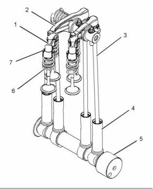
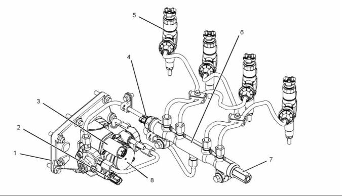
High Pressure Fuel System
g02450116
Illustration 29
Typical example
(1) Fuel injection pump
(2) Fuel temperature sensor
(3) Suction control valve for the fuel injection
pump
(4) Fuel pressure sensor
(5) Electronic unit injector
(6) Fuel manifold (rail)
(7) Pressure relief valve
(8) Fuel transfer pump
The fuel injection pump (1) feeds fuel to the
• Fuel transfer pump
high-pressure fuel manifold (rail) (6). The fuel is
at a pressure of 200 MPa (29000 psi). A pressure
sensor (4) in the high-pressure fuel manifold (rail) (6)
monitors the fuel pressure in the high-pressure fuel
manifold (rail) (6). The ECM controls a suction control
valve (3) in the fuel injection pump (1) in order to
maintain the actual pressure in the high-pressure fuel
manifold (6) at the desired level. The high-pressure
fuel is continuously available at each injector. The
ECM determines the correct time for activation of the
correct electronic unit injector (5) which allows fuel
to be injected into the cylinder. The leakoff fuel from
each injector passes into a drilling which runs along
the inside of the cylinder head. A pipe is connected
to the rear of the cylinder head in order to return the
leakoff fuel to the fuel tank.
• Secondary fuel filter
• Fuel injection pump
• Fuel injectors
• Fuel manifold
• Pressure relief valve
• Fuel pressure sensor
• Fuel temperature sensor
The following list contains examples of both
service and repairs when you must prime the
system:
Components of the Fuel Injection System
• A fuel filter is changed.
The fuel injection system has the following
mechanical components:
• A low-pressure fuel line is replaced.
• The fuel injection pump is replaced.
• The ECM is replaced.
• Primary filter/water separator
• Electric transfer pump
This document is printed from SPI². Not for RESALE
![]()
![]()
KENR9124-01
35
Systems Operation Section
Secondary Fuel Filter
For the correct procedure to prime the fuel system,
refer to Systems Operation, Testing and Adjusting,
“Fuel System - Prime”.
Primary Filter/Water Separator
g02214536
Illustration 31
Typical example
The secondary fuel filter (1) is located after the
primary fuel filter. The secondary fuel filter (1)
provides a 4 micron filtration level.
Fuel Pump Assembly
g02214535
Illustration 30
Typical example
The primary filter/water separator (1) is located
between the electric lift pump and the secondary fuel
filter. The primary filter/water separator (1) provides a
10 micron filtration level.
The primary filter/water separator can either be
engine mounted or supplied loose. The primary
filter/water separator is supplied with water in fuel
sensor (2).
g02450146
Illustration 32
Typical example
This document is printed from SPI². Not for RESALE
![]()
![]()
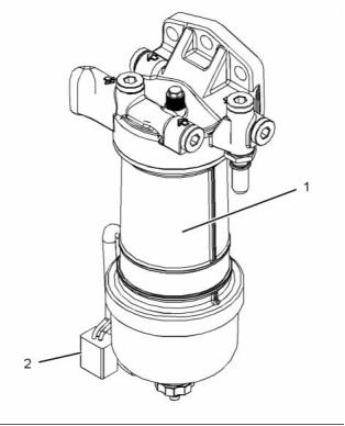
![]()
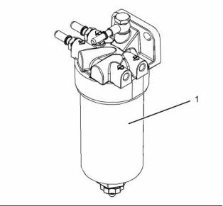
![]()
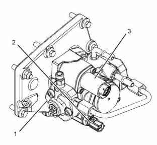
![]()
36
KENR9124-01
Systems Operation Section
The fuel pump assembly consists of a low-pressure
transfer pump and a high-pressure fuel injection
pump. The pump assembly is driven from a gear
in the front timing case at engine speed. The fuel
injection pump (1) has two plungers that are driven
by a camshaft. The fuel injection pump (1) delivers
a volume of fuel two times for each revolution. The
stroke of the plungers are fixed.
The injector will use only part of the fuel that is
delivered by each stroke of the pistons in the pump.
The suction control valve (3) for the fuel injection
pump (1) is controlled by the ECM. This maintains
the fuel pressure in the fuel manifold (rail) at the
correct level. A feature of the fuel injection pump (1)
allows fuel to return to the tank continuously.
The fuel temperature sensor (2) measures the
temperature of the fuel. The ECM receives the signal
from the fuel temperature sensor (2). The ECM
calculates the volume of fuel.
The fuel injection pump has the following
operation:
• Generation of high-pressure fuel
The fuel output of the fuel injection pump is controlled
by the ECM in response to changes in the demand of
fuel pressure.
Shutoff
The engine shuts off by preventing the electronic unit
injectors from injecting. The ECM then closes the
suction control valve to prevent the pressure in the
fuel manifold (rail) from increasing.
This document is printed from SPI². Not for RESALE
![]()
KENR9124-01
37
Systems Operation Section
Control
g02450148
Illustration 33
Typical example of the electrical control system for the fuel system
(1) Electronic Control Module (ECM)
(2) Throttle position sensor
(3) Wastegate regulator
(4) Fuel rail pressure sensor
(5) Inlet manifold pressure sensor
(6) Atmospheric pressure sensor
(7) Coolant temperature sensor
(8) Inlet manifold air temperature sensor
(9) Secondary speed/timing sensor
(10) Primary speed/timing sensor
(11) Fuel injection pump
(12) Suction control valve for the fuel
injection pump
(13) Fuel temperature sensor
(14) Electronic unit injectors
This document is printed from SPI². Not for RESALE
![]()
![]()
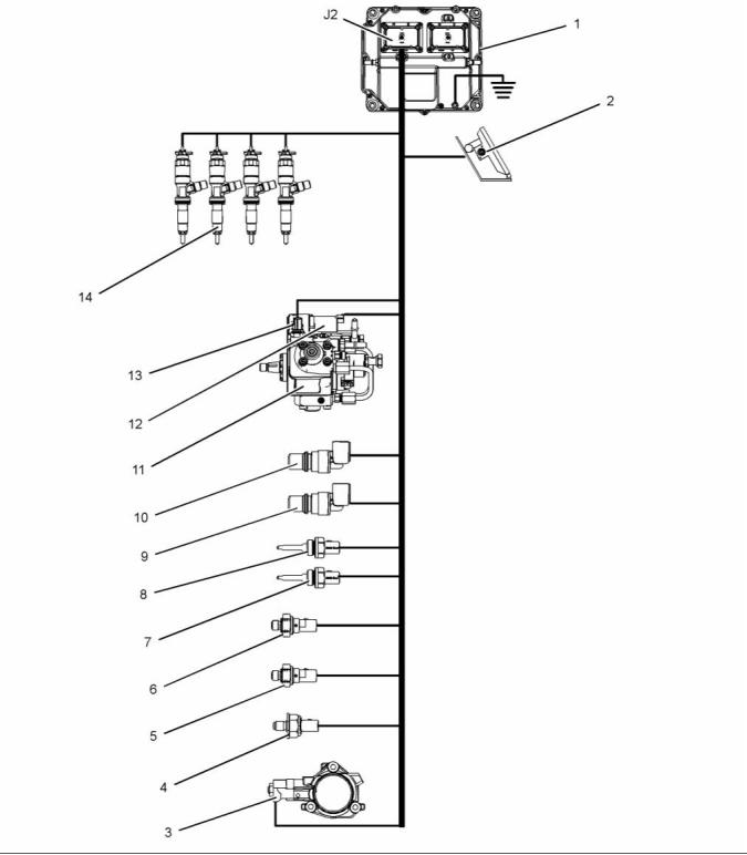
38
KENR9124-01
Systems Operation Section
The ECM determines the quantity, timing, and
pressure of the fuel in order to be injected into the
fuel injector.
The fuel injectors contain no serviceable parts apart
from the O-ring seal and the combustion washer. The
clamp and setscrew are serviced separately.
The ECM uses input from the sensors on the engine.
These sensors include the speed/timing sensors and
the pressure sensors.
The pressurized fuel from the fuel manifold is injected
into the combustion chamber by the electronic
unit injector. The desired injection timing, injection
quantity and injection pattern are controlled by the
ECM depending on engine operating conditions.
The ECM controls the timing and the flow of fuel by
actuating the injector solenoid.
The injection process is controlled using a two-way
valve. The supply of electrical current to the solenoid
controls the two-way valve. When the two-way valve
is not energized the out orifice is closed and there
is no fuel leak. In this condition the pressure in the
control chamber and the pressure at the nozzle
needle are the same. In this condition the spring
pressure on the command piston keeps the needle
closed.
The amount of fuel is proportional to the duration of
the signal to the injector solenoid.
The ECM controls the fuel pressure by increasing
or decreasing the flow of fuel from the fuel injection
pump.
Fuel Injectors
When an injection of fuel is required, the electrical
current from the ECM charges the solenoid, which in
turn energizes the two-way valve and lifts the valve.
When the valve lifts the valve uncovers the out orifice.
The fuel starts to flow and reduces the pressure in the
control chamber. When the pressure difference at the
nozzle needle exceeds the combined pressure of the
control chamber pressure and the spring pressure,
the nozzle lifts to start the injection process. The fuel
coming out of the nozzle is atomized and injected,
as a very fine spray.
When the injection needs to be stopped the electrical
current to the solenoid is cut off and the pressure
difference in the control chamber starts increasing.
The increased pressure difference stops the injection
process when the combined pressure exceeds the
nozzle pressure.
The electronic unit injectors can be instructed to inject
fuel multiple times during the combustion process. A
close pilot injection occurs before the main injection.
The close pilot injection helps to reduce NOx and
noise. The main injection period helps to increase the
torque of the engine. The after injection period helps
to reduce the amount of smoke that is produced.
g02290433
Illustration 34
Typical example
(1) Electrical connections
(2) Bolt
(3) Clamp
(4) Combustion washer
(5) O-ring
(6) Fuel inlet
Note: If a replacement electronic unit injector
is installed, the correct injector code must be
programmed into the electronic control module. Refer
to Troubleshooting, “Injector Code - Calibrate” for
more information. The code that is required is located
at Position (X). Record Code (X) before the electronic
unit injector is installed.
This document is printed from SPI². Not for RESALE
![]()
![]()

KENR9124-01
39
Systems Operation Section
Fuel Manifold
The electronic control system has the following
components:
• ECM
• Pressure sensor
• Temperature sensors
• Crankshaft speed/timing sensor
• Camshaft speed/timing sensor
• The suction control valve for the fuel injection pump
• Wastegate solenoid
• Electronic unit injectors
• Soot sensors
g02149309
Illustration 35
Typical example
The fuel manifold (2) stores high-pressure fuel from
the fuel injection pump. The high-pressure fuel will
flow to the injectors.
The fuel pressure sensor (1) measures the fuel
pressure in the fuel manifold (3).
The pressure relief valve (3) will prevent the fuel
pressure from getting too high.
The fuel pressure sensor must be replaced with the
fuel manifold (rail). The pressure relief valve can be
serviced as a separate component.
i04319689
Electronic Control System
Introduction
The engine is designed for electronic control. The
engine has an Electronic Control Module (ECM), a
fuel injection pump and electronic unit injectors. All
of these items are electronically controlled. There
are also a number of engine sensors. The engine is
equipped with an electronically controlled wastegate
system for the turbocharger. The ECM controls the
engine operating parameters through the software
within the ECM and the inputs from the various
sensors. The software contains parameters that
control the engine operation. The parameters include
all of the operating maps and customer-selected
parameters.
This document is printed from SPI². Not for RESALE
![]()
![]()
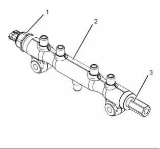
40
KENR9124-01
Systems Operation Section
Engines with Series Turbochargers
g02476176
Illustration 36
(1) Air cleaner
(12) Exhaust gas valve for the NOx
(25) Oil pressure sensor
(2) Air inlet temperature sensor
(3) Exhaust back pressure valve
(4) Diesel Oxidation Catalyst (DOC) and
Diesel Particulate Filter (DPF)
(5) Inlet temperature sensor for the DPF
(6) Soot sensor
(7) Exhaust Cooler for the NOx Reduction
System (NRS)
(8) Turbochargers
(9) Valve for the NOx Reduction System
(NRS)
(10) Temperature sensor for the NOx
Reduction System (NRS)
(11) Inlet pressure sensor for the NOx
Reduction System (NRS)
Reduction System (NRS)
(13) Air-to-air aftercooler
(14) Wastegate regulator
(15) Outlet pressure sensor for the NOx
Reduction System (NRS)
(16) Engine
(17) Coolant temperature sensor
(18) Crankshaft speed/timing sensor
(19) Electronic unit injectors
(20) Fuel cooler
(26) Atmospheric pressure sensor
(27) ECM
(28) Fuel transfer pump
(29) Primary fuel filter
(30) Fuel strainer
(31) Boost pressure sensor
(32) Inlet manifold temperature sensor
(33) Transfer pump inlet regulator
(34) Secondary fuel filter
(35) Fuel tank
(21) Fuel pressure relief valve
(22) Camshaft speed/timing sensor
(23) Fuel injection pump and fuel
temperature sensor
(24) Fuel pressure sensor
This document is printed from SPI². Not for RESALE
![]()
![]()
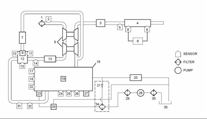
KENR9124-01
41
Systems Operation Section
Engines with a Single Turbocharger
g02420296
Illustration 37
Typical example
(1) Air cleaner
(12) Exhaust gas valve for the NOx
(25) Oil pressure sensor
(2) Air inlet temperature sensor
(3) Exhaust Cooler for the NOx Reduction
System (NRS)
(4) Exhaust back pressure valve
(5) Diesel Oxidation Catalyst (DOC) and
Diesel Particulate Filter (DPF)
(6) DPF inlet temperature sensor
(7) Soot sensor
(8) Turbocharger
(9) Valve for the NOx Reduction System
(NRS)
(10) Temperature sensor for the NOx
Reduction System (NRS)
(11) Inlet pressure sensor for the NOx
Reduction System (NRS)
Reduction System (NRS)
(13) Air-to-air aftercooler
(14) Wastegate regulator
(15) Outlet pressure sensor for the NOx
Reduction System (NRS)
(16) Engine
(17) Coolant temperature sensor
(18) Crankshaft speed/timing sensor
(19) Electronic unit injectors
(20) Fuel cooler
(26) Atmospheric pressure sensor
(27) ECM
(28) Fuel transfer pump
(29) Primary fuel filter
(30) Fuel strainer
(31) Inlet manifold pressure sensor
(32) Inlet manifold air temperature sensor
(33) Transfer pump inlet regulator
(34) Secondary fuel filter
(35) Fuel tank
(21) Fuel pressure relief valve
(22) Camshaft speed/timing sensor
(23) Fuel injection pump and fuel
temperature sensor
(24) Fuel pressure sensor
Sensor Locations for the Engine
The illustrations in this section show the typical
locations of the sensors for the industrial engine.
Specific engines may appear different from the
illustration due to differences in applications.
This document is printed from SPI². Not for RESALE
![]()
![]()
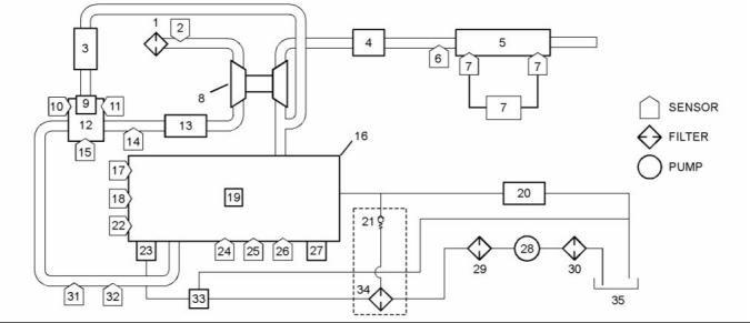
42
KENR9124-01
Systems Operation Section
g02476638
Illustration 38
(1) Coolant temperature sensor
(2) Fuel pressure sensor
(3) Inlet manifold temperature sensor
(4) Boost pressure sensor
(8) Engine oil pressure sensor
(9) Fuel temperature sensor
(10) Suction control valve for the fuel
injection pump
(13) Outlet pressure sensor for the NOx
Reduction System (NRS)
(14) Exhaust gas valve for the NOx
Reduction System (NRS)
(5) Electronic Control Module (ECM)
(6) Atmospheric pressure sensor
(7) Crankshaft speed/timing sensor
(11) Wastegate regulator
(12) Inlet pressure sensor for the NOx
Reduction System (NRS)
(15) Temperature sensor for the NOx
Reduction System (NRS)
This document is printed from SPI². Not for RESALE
![]()
![]()
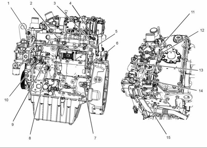
KENR9124-01
43
Systems Operation Section
g02476647
Illustration 39
(16) Exhaust back pressure valve
(17) Camshaft speed/timing sensor
(18) Water in fuel switch
(19) Oil level switch (if equipped)
(20) Electric fuel transfer pump
g02476653
Illustration 40
(1) Coolant temperature sensor
(2) Fuel pressure sensor
(3) Inlet manifold temperature sensor
(4) Boost pressure sensor
(5) Electronic Control Module (ECM)
This document is printed from SPI². Not for RESALE
![]()
![]()
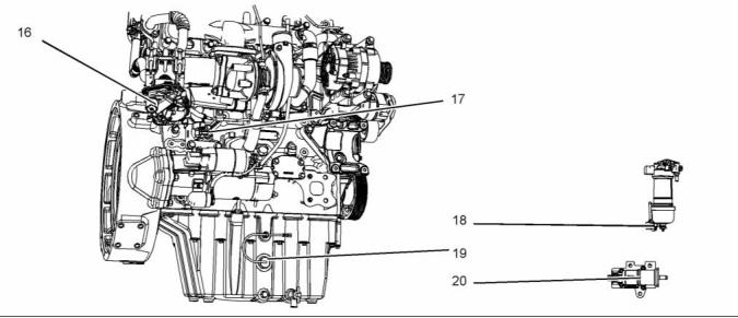
![]()
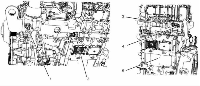
44
KENR9124-01
Systems Operation Section
g02476657
Illustration 41
(6) Atmospheric pressure sensor
(7) Crankshaft speed/timing sensor
(8) Engine oil pressure sensor
g02476662
Illustration 42
(9) Fuel temperature sensor
(10) Suction control valve for the fuel
injection pump
(11) Wastegate regulator
(12) Inlet pressure sensor for the NOx
Reduction System (NRS)
(13) Outlet pressure sensor for the NOx
Reduction System (NRS)
This document is printed from SPI². Not for RESALE
![]()
![]()
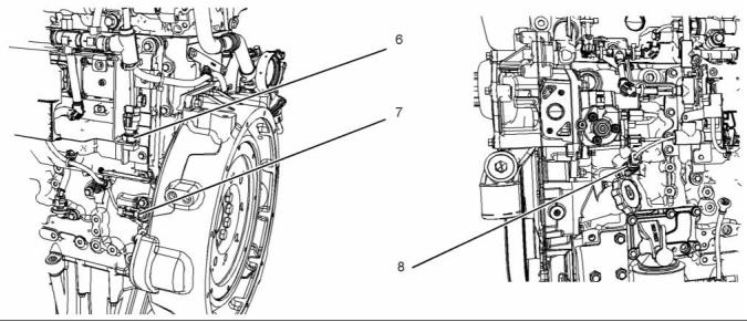
![]()
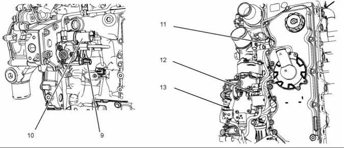
KENR9124-01
45
Systems Operation Section
g02476672
Illustration 43
(14) Exhaust gas valve for the NOx
Reduction System (NRS)
(15) Temperature sensor for the NOx
Reduction System (NRS)
(16) Exhaust back pressure valve
g02476674
Illustration 44
(17) Camshaft speed/timing sensor
This document is printed from SPI². Not for RESALE
![]()
![]()
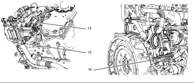
![]()
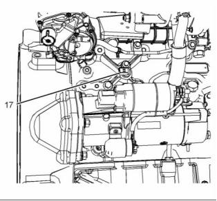
46
KENR9124-01
Systems Operation Section
g02476676
Illustration 45
(18) Water in fuel switch
(19) Oil level switch (if equipped)
(20) Electric fuel transfer pump
Sensor Locations for the Clean
Emissions Module
g02395776
Illustration 46
(1) Temperature sensor
(2) Connector for temperature sensor
(3) Soot sensor connection
(4) Aftertreatment identification module
(5) Soot sensor connection
(6) Soot sensor module
Note: The location of the soot sensor module will
depend on the application.
This document is printed from SPI². Not for RESALE
![]()
![]()
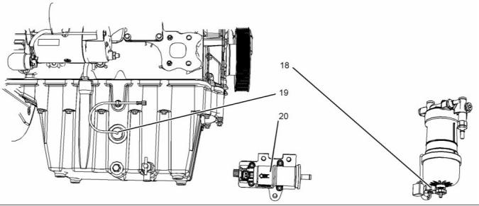
![]()
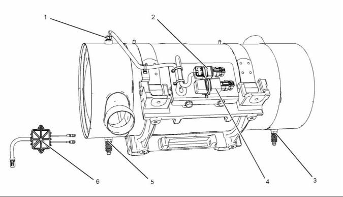
KENR9124-01
47
Systems Operation Section
ECM
The ECM has an excellent record of reliability. Any
problems in the system are most likely to be the
connectors and the wiring harness. The ECM should
be the last item in troubleshooting the engine.
The programmable software contains all the fuel
setting information. The information determines the
engine performance.
Flash programming is the method of programming
or updating the programmable software. Refer
to Troubleshooting, “Flash Programming” for
the instructions on the flash programming of the
programmable software.
The ECM is sealed and the ECM needs no routine
adjustment or maintenance.
Engine Speed
The electronic controls determine the injection timing,
the amount of fuel that is delivered to the cylinders
and the intake manifold pressure if an electronically
controlled wastegate is installed. These decisions
are based on the actual conditions and the desired
conditions at any given time.
The ECM has software that compares the desired
engine speed to the actual engine speed. The actual
engine speed is determined through the crankshaft
speed/timing sensor and the camshaft speed/timing
sensor. If the desired engine speed is greater than
the actual engine speed, the ECM will instruct the
electronic unit injector to inject more fuel in order to
increase engine speed.
g01926054
Illustration 47
Typical example
The Electronic Control Module (ECM) (1) functions
as a governor and a computer for the fuel system.
The ECM receives signals from the sensors in order
to control the timing and the engine speed.
Timing Considerations
The electronic system consists of the ECM, the
engine sensors, and inputs from the parent machine.
The ECM is the computer. The personality module
is the software for the computer. The personality
module contains the operating maps. The operating
maps define the following characteristics of the
engine:
Once the ECM has determined the amount of fuel
that is required, the software must determine the
timing of the fuel injection. Fuel injection timing is
determined by the ECM after considering input from
the following components:
• Engine coolant temperature sensor
• Engine rating
• The sensor for the intake manifold air temperature
• The sensor for the intake manifold pressure
• Torque curves
• High and low idle speed (rpm)
• Emissions
• Injection timing
The factory passwords restrict changes to authorized
personnel. Factory passwords are required to clear
any event code. Refer to Troubleshooting, “Factory
Passwords” for more information on the passwords.
This document is printed from SPI². Not for RESALE
![]()
![]()
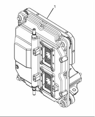
48
KENR9124-01
Systems Operation Section
Diagnostic Codes
At start-up, the ECM determines the top center
position of the number 1 cylinder from the secondary
speed/timing sensor in the fuel injection pump.
The ECM decides when fuel injection should occur
relative to the top center position. The ECM optimizes
engine performance by control of each of the
electronic unit injectors so that the required amount
of fuel is injected at the precise point of the engines
cycle. The electronic unit injectors are supplied
high-pressure fuel from the fuel manifold. The ECM
also provides the signal to the solenoid in the fuel
injection pump. The solenoid in the fuel injection
pump controls a valve in the fuel injection pump. This
valve controls the pressure in the fuel manifold. Fuel
that is not required for the engine is diverted away
from the fuel injection pump back to the fuel tank.
When the ECM detects an electronic system problem,
the ECM generates a diagnostic code. Also, the ECM
logs the diagnostic code in order to indicate the time
of the problems occurrence. The ECM also logs the
number of occurrences of the problem. Diagnostic
codes are provided in order to indicate that the ECM
has detected an electrical problem or an electronic
problem with the engine control system. In some
cases, the engine performance can be affected when
the condition that is causing the code exists.
If the operator indicates that a performance problem
occurs, the diagnostic code may indicate the cause
of the problem. Use a laptop computer to access
the diagnostic codes. The problem should then be
corrected.
The ECM adjusts injection timing and fuel pressure
for the best engine performance, the best fuel
economy, and the best control of exhaust emissions.
The actual timing can be viewed with an electronic
service tool. Also, the desired timing can be viewed
with an electronic service tool.
Event Codes
Event Codes are used to indicate that the ECM has
detected an abnormal engine operating condition.
The ECM will log the occurrence of the event code.
This does not indicate an electrical malfunction or
an electronic malfunction. If the temperature of the
coolant in the engine is higher than the permitted
limit, then the ECM will detect the condition. The
ECM will then log an event code for the condition.
Fuel Injection
The programmable software inside the ECM sets
certain limits on the amount of fuel that can be
injected.
The FRC Limit is a limit that is based on intake
manifold air pressure and engine rpm. The FRC
Limit is used to control the air/fuel ratio in order to
control the engines exhaust emissions. When the
ECM senses a higher intake manifold air pressure,
the ECM increases the FRC Limit. A higher intake
manifold air pressure indicates that there is more air
in the cylinder. When the ECM increases the FRC
Limit, the ECM allows more fuel into the cylinder.
Passwords
System Configuration Parameters are protected by
factory passwords. This will prevent unauthorized
reprogramming of the system and the unauthorized
removal of logged events. Factory passwords are
calculated on a computer system that is available
only to Perkins distributors. Since factory passwords
contain alphabetic characters, only an electronic
service tool may change System Configuration
Parameters. System Configuration Parameters affect
the power rating or the emissions. Passwords also
allow the customer to control certain programmable
engine parameters.
The Rated Fuel Limit is a limit that is based on the
power rating of the engine and on the engine rpm.
The Rated Fuel Limit enables the engine power and
torque outputs to conform to the power and torque
curves of a specific engine model.
Refer to Troubleshooting, “Programming Parameters”
and Troubleshooting, “Factory Passwords”.
These limits are in the programmable software and
these limits cannot be changed.
The ECM controls the following characteristics:
• Boost pressure
• Operation of the NOx reduction system
This document is printed from SPI². Not for RESALE
![]()
KENR9124-01
49
Systems Operation Section
Speed/Timing Sensors
The secondary speed/timing sensor is located on the
right-hand side of the cylinder block toward the rear
of the engine. The secondary speed/timing sensor
generates a signal that is related to the camshaft
position. The secondary speed/timing sensor detects
the movement of the teeth on the timing ring (2) for
the camshaft. The signal that is generated by the
speed/timing sensor is transmitted to the ECM. The
ECM calculates the speed and the rotational position
of the engine by using the signal. The secondary
speed/timing sensor is required for starting purposes.
g02155463
Illustration 48
Typical example
The primary speed/timing sensor is located on the
left-hand side of the cylinder block close to the
flywheel housing. The primary speed/timing sensor
generates a signal by detecting the movement of the
teeth that are located on the crankshaft timing ring
(1). The signal that is generated by the speed/timing
sensor is transmitted to the ECM. The ECM uses the
signal from the speed/timing sensor to calculate the
position of the crankshaft. The signal is also used to
determine the engine speed.
g02476196
Illustration 49
Typical example
This document is printed from SPI². Not for RESALE
![]()
![]()
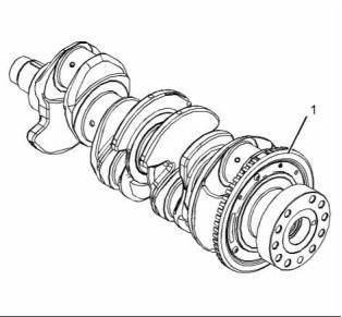
![]()
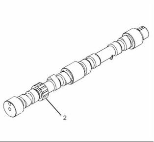
50
KENR9124-01
Systems Operation Section
g01878676
Illustration 50
Schematic for speed/timing sensor
When the engine is cranking, the ECM uses the
signal from the speed/timing sensor on the camshaft.
When the engine is running the ECM uses the signal
from the speed/timing sensor on the crankshaft. This
speed/timing sensor is the primary source of the
engine position.
Pressure Sensors
g02139716
Illustration 51
Schematic for the pressure sensors
The boost pressure sensor and the engine oil
pressure sensor are active sensors.
The boost pressure sensor provides the ECM with a
measurement of inlet manifold pressure in order to
control the air/fuel ratio. This will reduce the engine
smoke during transient conditions.
This document is printed from SPI². Not for RESALE
![]()
![]()
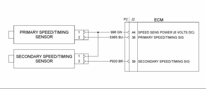
![]()
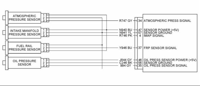
KENR9124-01
51
Systems Operation Section
The operating range of the boost pressure sensors is
39 to 400 kPa (6 to 58 psi).
The engine oil pressure sensor provides the ECM
with a measurement of engine oil pressure. The ECM
can warn the operator of possible conditions that can
damage the engine. This includes the detection of
an oil filter that is blocked.
The operating range for the engine oil pressure
sensor ......................... 13 to 1200 kPa (2 to 174 psi)
Temperature Sensors
g02139713
Illustration 52
Schematic for the engine temperature sensors
g02139706
Illustration 53
Schematic for the temperature sensors for the engine aftertreatment system
The air inlet temperature sensor and the coolant
temperature sensor are passive sensors. Each
sensor provides a temperature input to the ECM. The
ECM controls following operations:
The operating range for the sensors ... −40° to 125°C
(−40° to 257°F)
The operating range for the fuel temperature
sensor ....................... −40° to 120°C (−40° to 248°F)
• Fuel delivery
The sensors are also used for engine monitoring.
• Injection timing
This document is printed from SPI². Not for RESALE
![]()
![]()
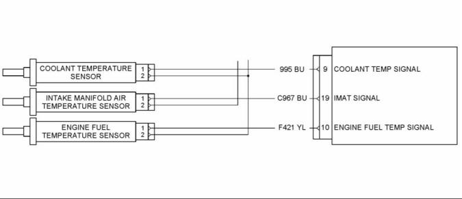
![]()
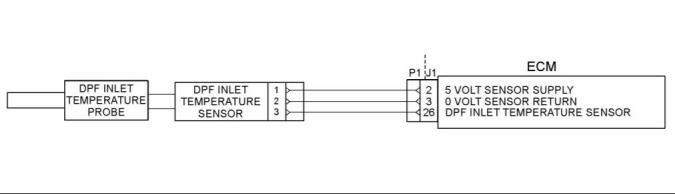
52
KENR9124-01
Systems Operation Section
Sensors for the NOx Reduction
System (NRS)
g02139786
Illustration 54
A typical example of a schematic of the position sensors for the NOx Reduction System (NRS)
i04252009
Power Sources
Introduction
The engine supplies power to the ECM. The ECM
powers the following components:
• All sensors on the engine
• The suction control valve for the fuel injection pump
• The solenoid for the wastegate
• Diagnostic connector
• Electronic unit injectors
The glow plugs are powered directly from the battery.
This document is printed from SPI². Not for RESALE
![]()
![]()
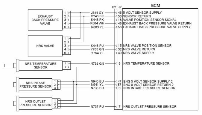
KENR9124-01
53
Systems Operation Section
ECM Power Supply
g02423278
Illustration 55
Typical example
The power supply to the ECM and the system is
drawn from the 24 V or the 12 V battery. The power
supply for the ECM has the following components:
• Battery
• Disconnect switch
• Ignition keyswitch
• Fuses
• Ground bolt
• ECM connector
• Machine interface connector
The Schematic for the ECM shows the main
components for a typical power supply circuit. Battery
voltage is normally connected to the ECM. The input
from the ignition keyswitch turns on the ECM.
The wiring harness can be bypassed for
troubleshooting purposes.
The display screen on the electronic service tool can
be used in order to check the voltage supply.
This document is printed from SPI². Not for RESALE
![]()
![]()
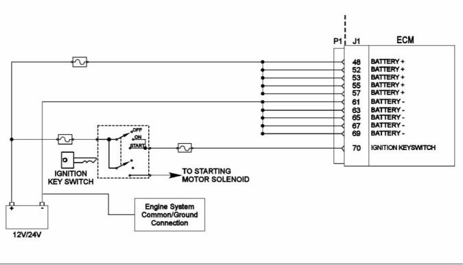
54
KENR9124-01
Systems Operation Section
Power Supply for the Pressure
Sensors
g02139716
Illustration 56
Schematic for pressure sensors
The ECM supplies 5 VDC volts through the ECM
connector to each sensor. The power supply is
protected against short circuits. A short in a sensor or
a wiring harness will not cause damage to the ECM.
This document is printed from SPI². Not for RESALE
![]()
![]()
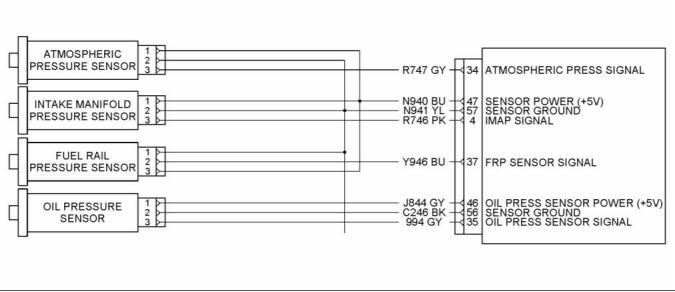
KENR9124-01
55
Systems Operation Section
Power Supply for the Glow plugs
g02149319
Illustration 57
Typical example
Air-To-Air Aftercooler – An air-to-air aftercooler is a
device that is used on turbocharged engines in order
to cool inlet air that has undergone compression. The
inlet air is cooled after the inlet air passes through
the turbocharger. The inlet air is passed through an
aftercooler (heat exchanger) that uses ambient air for
cooling. The inlet air that has been cooled advances
to the inlet manifold.
i04248617
Glossary of Electronic Control
Terms
Active Diagnostic Code – An active diagnostic
code alerts the operator or the service technician that
an electronic system malfunction is currently present.
Refer to the term “Diagnostic Trouble Code” in this
glossary.
Alternating Current (AC) – Alternating current is an
electric current that reverses direction at a regular
interval that is reoccurring.
Before Top Center (BTC) – BTC is the 180 degrees
of crankshaft rotation before the piston reaches the
top center position in the normal direction of rotation.
Aftertreatment – Aftertreatment is a system that is
used to remove pollutants from exhaust gases. The
system consists of a Diesel Oxidation Catalyst (DOC)
and a Catalyzed Diesel Particulate Filter (CDPF).
Inlet Manifold Pressure – The difference between
the turbocharger outlet pressure and atmospheric
pressure is commonly referred to as inlet manifold
pressure. The sensor for the inlet manifold air
pressure measures the amount of boost.
This document is printed from SPI². Not for RESALE
![]()
![]()
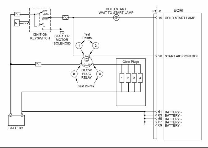
56
KENR9124-01
Systems Operation Section
Breakout Harness – The breakout harness is a
test harness that is designed to connect into the
engine harness. This connection allows a normal
circuit operation and the connection simultaneously
provides a Breakout T in order to measure the
signals.
Desired Engine Speed – The desired engine speed
is input to the electronic governor within the ECM.
The electronic governor uses the signal from the
throttle position sensor, the engine speed/timing
sensor, and other sensors in order to determine the
desired engine speed.
Bypass Circuit – A bypass circuit is a circuit that is
used as a substitute circuit for an existing circuit. A
bypass circuit is typically used as a test circuit.
Diagnostic Trouble Code – A diagnostic trouble
code is sometimes referred to as a fault code. These
codes indicate an electronic system malfunction.
CAN Data Link (see also J1939 CAN Data Link) –
The CAN Data Link is a serial communications
port that is used for communication with other
microprocessor-based devices.
Diagnostic Lamp – A diagnostic lamp is sometimes
called the check engine light. The diagnostic lamp
is used to warn the operator of the presence of an
active diagnostic code. The diagnostic lamps are
red and orange. The lamp may not be included in
all applications.
Catalyzed Diesel Particulate Filter – The Catalyzed
Diesel Particulate Filter (CDPF) filters particulates
from the exhaust gases. A coating on the internal
surfaces reacts with the hot exhaust gases in order
to burn off the particulates. This process prevents the
CDPF from becoming blocked with soot.
Diesel Oxidation Catalyst – The Diesel Oxidation
Catalyst is also known as the (DOC). The DOC is a
device in the exhaust system that oxidizes certain
elements in the exhaust gases. These elements
can include carbon monoxide (CO), hydrocarbons
and the soluble organic fraction (SOF) of particulate
matter.
Code – Refer to “Diagnostic Trouble Code”.
Cold Mode – Cold mode is a mode for cold starting
and for cold engine operation. This mode is used for
engine protection, reduced smoke emissions, and
faster warm-up time.
Digital Sensor Return – The common line (ground)
from the ECM is used as ground for the digital
sensors.
Communication Adapter Tool – The
communication adapter provides a communication
link between the ECM and the Electronic Service
Tool.
Digital Sensors – Digital sensors produce a pulse
width modulated signal. Digital sensors are supplied
with power from the ECM.
Digital Sensor Supply – The power supply for the
digital sensors is provided by the ECM.
Coolant Temperature Sensor – The coolant
temperature sensor detects the engine coolant
temperature for all normal operating conditions and
for engine monitoring.
Direct Current (DC) – Direct current is the type of
current that flows consistently in only one direction.
Customer Specified Parameters – A customer
specified parameter is a parameter that can be
changed in the ECM with the Electronic Service Tool.
A customer specified parameter's value is set by
the customer. These parameters are protected by
customer passwords.
DT, DT Connector, or Deutsch DT – This is a
type of connector that is used on this engine. The
connectors are manufactured by Deutsch.
Duty Cycle – See “Pulse Width Modulation”.
Electronic Engine Control – The electronic
engine control is a complete electronic system.
The electronic engine control monitors the engine
operation under all conditions. The electronic engine
control also controls the engine operation under all
conditions.
Data Link – The Data Link is a serial communication
port that is used for communication with other
microprocessor-based devices.
Derate – Certain engine conditions will generate
event codes. Also, engine derates may be applied.
The map for the engine derate is programmed into
the ECM software. The derate can be one or more
of three types: reduction of rated power, reduction of
rated engine speed, and reduction of rated machine
speed for OEM products.
Electronic Control Module (ECM) – The ECM
is the control computer of the engine. The ECM
provides power to the electronics. The ECM monitors
data that is input from the sensors of the engine. The
ECM acts as a governor in order to control the speed
and the power of the engine.
This document is printed from SPI². Not for RESALE
![]()
KENR9124-01
57
Systems Operation Section
Electronic Service Tool – The electronic service
tool is used for diagnosing various electronic controls
and the electronic service tool is also used for
programming various electronic controls.
5 – The current is below normal or the circuit is open.
6 – The current is above normal or the circuit is
grounded.
Engine Monitoring – Engine Monitoring is the part
of the electronic engine control that monitors the
sensors. This also warns the operator of detected
problems.
7 – The mechanical system is not responding
properly.
8 – There is an abnormal frequency, an abnormal
pulse width, or an abnormal time period.
Engine Oil Pressure Sensor – The engine oil
pressure sensor measures engine oil pressure. The
sensor sends an electronic signal to the ECM that is
dependent on the engine oil pressure.
9 – There has been an abnormal update.
10 – There is an abnormal rate of change.
11 – The failure mode is not identifiable.
12 – The device or the component is damaged.
13 – The device requires calibration.
Engine Speed/Timing Sensor – An engine
speed/timing sensor is a hall effect switch that
provides a digital signal to the ECM. The ECM
interprets this signal as the crankshaft position and
the engine speed. Two sensors are used to provide
the speed and timing signals to the ECM. The primary
sensor is associated with the crankshaft and the
secondary sensor is associated with the camshaft.
14 – There is a special instruction for the device.
15 – The signal from the device is high (least severe).
Estimated Dynamic Timing – Estimated dynamic
timing is the estimate of the actual injection timing
that is calculated by the ECM.
16 – The signal from the device is high (moderate
severity).
Event Code – An event code may be activated
in order to indicate an abnormal engine operating
condition. These codes usually indicate a mechanical
problem instead of an electrical system problem.
17 – The signal from the device is low (least severe).
18 – The signal from the device is low (moderate
severity).
Exhaust Back Pressure Valve – The exhaust back
pressure valve regulates the gas pressure in the
exhaust system. The valve can restrict the flow of
exhaust gases in order to increase the exhaust back
pressure. An increase in exhaust back pressure will
increase the temperature of the exhaust gases which
will improve the process that burns off the soot in the
CDPF.
19 – There is an error in the data from the device.
31 – The device has failed and the engine has shut
down.
Flash File – This file is software that is inside
the ECM. The file contains all the instructions
(software) for the ECM and the file contains the
performance maps for a specific engine. The file may
be reprogrammed through flash programming.
Failure Mode Identifier (FMI) – This identifier
indicates the type of failure that is associated with
the component. The FMI has been adopted from the
SAE practice of J1587 diagnostics. The FMI follows
the parameter identifier (PID) in the descriptions of
the fault code. The descriptions of the FMIs are in
the following list.
Flash Programming – Flash programming is the
method of programming or updating an ECM with
an electronic service tool over the data link instead
of replacing components.
Fuel Injection Pump – This item is sometimes
referred to as the High Pressure Fuel Pump. This
is a device that supplies fuel under pressure to the
fuel manifold (rail).
0 – The data is valid but the data is above the normal
operational range.
1 – The data is valid but the data is below the normal
operational range.
Fuel Manifold (Rail) – This item is sometimes
referred to as the High Pressure Fuel Rail. The fuel
rail supplies fuel to the electronic unit injectors. The
fuel injection pump and the fuel pressure sensor work
with the ECM in order to maintain the desired fuel
pressure in the fuel rail. This pressure is determined
by calibration of the engine in order to enable
the engine to meet emissions and performance
requirements.
2 – The data is erratic, intermittent, or incorrect.
3 – The voltage is above normal or the voltage is
shorted high.
4 – The voltage is below normal or the voltage is
shorted low.
This document is printed from SPI². Not for RESALE
![]()
58
KENR9124-01
Systems Operation Section
Fuel Manifold (Rail) Pressure Sensor – The fuel
rail pressure sensor sends an electronic signal to the
ECM that is dependent on the pressure of the fuel
in the fuel rail.
Injector Trim Codes – Injector trim codes are codes
that contain 30 characters. The codes are supplied
with new injectors. The code is input through the
electronic service tool into the ECM. The injector trim
codes compensate for variances in manufacturing
of the electronic unit injector and for the life of the
electronic unit injector.
Fuel Pump – See “Fuel Injection Pump”.
Fuel Ratio Control (FRC) – The FRC is a limit that
is based on the control of the fuel to the air ratio. The
FRC is used for emission control. When the ECM
senses a higher turbocharger outlet pressure, the
ECM increases the limit for the FRC in order to allow
more fuel into the cylinders.
Inlet Manifold Air Temperature Sensor – The
inlet manifold air temperature sensor detects the
air temperature in the inlet manifold. The ECM
monitors the air temperature and other data in the
inlet manifold in order to adjust injection timing and
other performance functions.
The Suction Control Valve for the Fuel Injection
Pump – This is sometimes referred to as the High
Pressure Fuel Rail Pump Sunction Control Valve.
This is a control device in the fuel injection pump.
The ECM controls the pressure in the fuel rail by
using this valve to divert excess fuel from the pump
to the fuel tank.
Inlet Manifold Pressure Sensor – The Inlet
Manifold Pressure Sensor measures the pressure in
the inlet manifold. The pressure in the inlet manifold
may be different to the pressure outside the engine
(atmospheric pressure). The difference in pressure
may be caused by an increase in air pressure by a
turbocharger.
Full Load Setting (FLS) – The FLS is the number
that represents the fuel system adjustment. This
adjustment is made at the factory in order to fine-tune
the fuel system. The correct value for this parameter
is stamped on the engine information ratings plate.
This parameter must be programmed.
Integrated Electronic Controls – The engine is
designed with the electronic controls as a necessary
part of the system. The engine will not operate
without the electronic controls.
J1939 CAN Data Link – This data link is a SAE
standard diagnostic communications data link that is
used to communicate between the ECM and other
electronic devices.
Glow Plug – The glow plug is an optional starting aid
for cold conditions. One glow plug is installed in each
combustion chamber in order to improve the ability of
the engine to start. The ECM uses information from
the engine sensors such as the engine temperature
to determine when the glow plug relay must provide
power to each glow plug. Each of the glow plugs
then provides a very hot surface in the combustion
chamber in order to vaporize the mixture of air and
fuel. This improves ignition during the compression
stroke of the cylinder.
Logged Diagnostic Codes – Logged diagnostic
codes are codes which are stored in the memory.
These codes are an indicator of possible causes for
intermittent problems. Refer to the term “Diagnostic
Trouble Codes” for more information.
NOx Reduction System – The NOx Reduction
System recycles a portion of the exhaust gases back
into the inlet air in order to reduce the amount of
oxides of nitrogen (NOx) in the exhaust gases. The
recycled exhaust gas passes through a cooler before
being introduced into the inlet air.
Glow Plug Relay – The glow plug relay is controlled
by the ECM in order to provide high current to the
glow plugs that are used in the starting aid system.
Harness – The harness is the bundle of wiring
(loom) that connects all components of the electronic
system.
OEM – OEM is an abbreviation for the Original
Equipment Manufacturer. This is the manufacturer of
the machine or the vehicle that uses the engine.
Hertz (Hz) – Hertz is the measure of frequency in
cycles per second.
Open Circuit – An open circuit is a condition that is
caused by an open switch, or by an electrical wire
or a connection that is broken. When this condition
exists, the signal or the supply voltage can no longer
reach the intended destination.
High Pressure Fuel Rail Pump – See “Fuel
Injection Pump”.
High Pressure Fuel Rail Pump Suction Control
Valve – See “The Suction Control Valve for the Fuel
Injection Pump”.
Parameter – A parameter is a value or a limit that
is programmable. This helps determine specific
characteristics or behaviors of the engine.
High Pressure Fuel Rail – See “Fuel Manifold
(Rail)”.
This document is printed from SPI². Not for RESALE
![]()
KENR9124-01
59
Systems Operation Section
Password – A password is a group of numeric
characters or a group of alphanumeric characters
that is designed to restrict access to parameters. The
electronic system requires correct passwords in order
to change some parameters (Factory Passwords).
Refer to Troubleshooting, “Factory Passwords” for
more information.
Relay – A relay is an electromechanical switch. A
flow of electricity in one circuit is used to control the
flow of electricity in another circuit. A small , current or
voltage is applied to a relay in order to switch a much
larger current or voltage.
Secondary Speed/Timing Sensor – This sensor
determines the position of the camshaft during engine
operation. If the primary speed/timing sensor fails
during engine operation, the secondary speed/timing
sensor is used to provide the signal.
Programmable Software – The software is
programmed into the ECM. The software contains
all the instructions (software) for the ECM and the
software contains the performance maps for a
specific engine. The software may be reprogrammed
through flash programming.
Sensor – A sensor is used to detect a change in
the pressure, in the temperature, or in mechanical
movement. When any of these changes are detected,
a sensor converts the change into an electrical signal.
Power Cycling – Power cycling refers to the action
of cycling the keyswitch from any position to the OFF
position, and to the START/RUN position.
Short Circuit – A short circuit is a condition that has
an electrical circuit that is inadvertently connected to
an undesirable point. An example of a short circuit
is a wire which rubs against a vehicle frame and
this rubbing eventually wears off the wire insulation.
Electrical contact with the frame is made and a short
circuit results.
Primary Speed/Timing Sensor – This sensor
determines the position of the crankshaft during
engine operation. If the primary speed/timing
sensor fails during engine operation, the secondary
speed/timing sensor is used to provide the signal.
Pulse Width Modulation (PWM) – The PWM is a
signal that consists of pulses that are of variable
width. These pulses occur at fixed intervals. The ratio
of “TIME ON” versus total “TIME OFF” can be varied.
This ratio is also referred to as a duty cycle.
Signal – The signal is a voltage or a waveform that
is used in order to transmit information typically from
a sensor to the ECM.
Suction Control Valve (SCV) – The SCV is a
control device in the high-pressure fuel pump. The
ECM controls the pressure in the fuel rail by using
this valve to control the amount of fuel that enters
the chambers in the pump.
Supply Voltage – The supply voltage is a continuous
voltage that is supplied to a component in order to
provide the electrical power that is required for the
component to operate. The power may be generated
by the ECM or the power may be battery voltage that
is supplied by the engine wiring.
System Configuration Parameters – System
configuration parameters are parameters that affect
emissions and/or operating characteristics of the
engine.
g00284479
Illustration 58
Rated Fuel Limit – This is a limit that is based on
the power rating of the engine and on the engine rpm.
The Rated Fuel Limit enables the engine power and
torque outputs to conform to the power and torque
curves of a specific engine model. These limits are in
the flash file and these limits cannot be changed.
Tattletale – Certain parameters that affect the
operation of the engine are stored in the ECM.
These parameters can be changed by use of the
electronic service tool. The tattletale logs the number
of changes that have been made to the parameter.
The tattletale is stored in the ECM.
Reference Voltage – Reference voltage is a
regulated voltage and a steady voltage that is
supplied by the ECM to a sensor. The reference
voltage is used by the sensor to generate a signal
voltage.
“T” Harness – This harness is a test harness that
is designed to permit normal circuit operation and
the measurement of the voltage simultaneously.
Typically, the harness is inserted between the two
ends of a connector.
Throttle Position – The throttle position is the
interpretation by the ECM of the signal from the
throttle position sensor or the throttle switch.
This document is printed from SPI². Not for RESALE
![]()
![]()
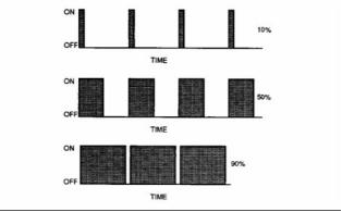
60
KENR9124-01
Systems Operation Section
Throttle Position Sensor – The throttle position
sensor is an electronic sensor that is usually
connected to an accelerator pedal or a hand lever.
This sensor sends a signal to the ECM that is used
to calculate desired engine speed.
Throttle Switch – The throttle switch sends a signal
to the ECM that is used to calculate desired engine
speed.
Top Center Position – The top center position refers
to the crankshaft position when the engine piston
position is at the highest point of travel. The engine
must be turned in the normal direction of rotation in
order to reach this point.
Total Tattletale – The total tattletale is the total
number of changes to all the parameters that are
stored in the ECM.
Wait To Start Lamp – This is a lamp that is included
in the cold starting aid circuit in order to indicate when
the wait to start period has expired. The glow plugs
have not deactivated at this point in time.
Wastegate – This is a device in a turbocharged
engine that controls the maximum boost pressure
that is provided to the inlet manifold.
Wastegate Regulator – The wastegate regulator
controls the pressure in the intake manifold to a
value that is determined by the ECM. The wastegate
regulator provides the interface between the ECM
and the wastegate.
This document is printed from SPI². Not for RESALE
![]()
KENR9124-01
61
Testing and Adjusting Section
Testing and Adjusting
Section
i04103212
Air in Fuel - Test
Fuel System
Table 1
Required Tools
Part Description
Part
Number
i04081693
Tool
Qty
Fuel System - Inspect
A
T400024
Sight gauge
1
NOTICE
NOTICE
Ensure that all adjustments and repairs that are
carried out to the fuel system are performed by
authorized personnel that have the correct train-
ing.
Ensure that all adjustments and repairs that are
carried out to the fuel system are performed by
authorized personnel that have the correct train-
ing.
Before beginning ANY work on the fuel system, re-
fer to Operation and Maintenance Manual, “Gen-
eral Hazard Information and High Pressure Fuel
Lines” for safety information.
Before beginning ANY work on the fuel system, re-
fer to Operation and Maintenance Manual, “Gen-
eral Hazard Information and High Pressure Fuel
Lines” for safety information.
Refer to Systems Operation, Testing and Adjust-
ing, “Cleanliness of Fuel System Components” for
detailed information on the standards of cleanli-
ness that must be observed during ALL work on
the fuel system.
Refer to Systems Operation, Testing and Adjust-
ing, “Cleanliness of Fuel System Components” for
detailed information on the standards of cleanli-
ness that must be observed during ALL work on
the fuel system.
Note: Ensure that the tools are stored with the caps
A problem with the components that transport fuel
to the engine can cause low fuel pressure. This can
decrease engine performance.
in place. Store the tools in a clean plastic bag.
1. Ensure that the fuel level in the fuel tank is above
the level of the suction pipe in the fuel tank.
1. Check the fuel level in the fuel tank. Ensure that
the vent in the fuel cap is not filled with dirt.
2. Inspect the fuel system thoroughly for leaks. If
necessary, repair the fuel system.
2. Check that the valve in the fuel return line is open
before the engine is started.
3. Check all low-pressure fuel lines from the fuel
tank for restrictions. Replace any damaged
components.
3. Check all low-pressure fuel lines for fuel leakage.
The fuel lines must be free from restrictions and
faulty bends. Verify that the fuel return line is not
collapsed.
4. Prime the fuel system. Refer to Operation and
Maintenance Manual, “Fuel System - Prime” for
the correct procedure. If the electric fuel transfer
pump is not operating, refer to Troubleshooting,
“Fuel Pump Relay Circuit - Test”.
4. Install new fuel filters.
5. Cut the old filter open with a suitable filter cutter.
Inspect the filter for excess contamination.
Determine the source of the contamination. Make
the necessary repairs.
5. Start the engine. Refer to Operation and
Maintenance Manual, “Starting the Engine” for
the correct procedure. Check if the problem has
been resolved. Run the engine at low idle speed
for 5 minutes.
6. Stop the engine. Refer to Operation and
Maintenance Manual, “Stopping the Engine” for
the correct procedure.
This document is printed from SPI². Not for RESALE
![]()
![]()
![]()
![]()
![]()
62
KENR9124-01
Testing and Adjusting Section
g02305093
Illustration 59
Typical example
7. If necessary, remove the low-pressure fuel line
from the retaining clips. Remove the low-pressure
fuel line from the inlet connection (1) of the
secondary fuel filter base.
Note: Ensure that the low-pressure fuel lines are
not deformed.
g02352952
Illustration 60
8. Connect Tooling (A) to the low-pressure fuel line
and the secondary fuel filter base. Connect the
open end of the tube to the inlet connection (1) of
the secondary fuel filter base. Ensure that Tooling
(A) is secured and clear of rotating parts.
9. Prime the fuel system. Refer to Operation and
Maintenance Manual, “Fuel System - Prime” for
the correct procedure.
10. Start the engine. Refer to Operation and
Maintenance Manual, “Starting the Engine” for the
correct procedure. Refer to steps 10.a to 10.d for
the procedure for testing the air in fuel.
This document is printed from SPI². Not for RESALE
![]()
![]()
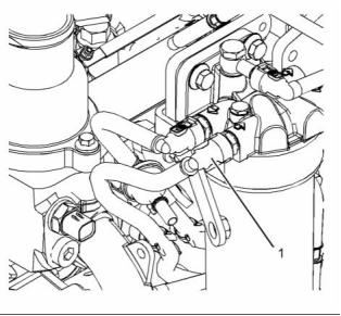
![]()
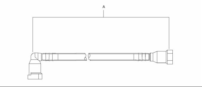
KENR9124-01
63
Testing and Adjusting Section
a. Run the engine a low idle speed.
b. Run the engine for 2 minutes. There should
be no air in the fuel flow through the sight
tube. Small bubbles that are spaced more
than 2.5 cm (1.0 inch) are acceptable. Do not
manipulate the connections during the test for
the air in fuel.
c. The presence of large bubbles or a continuous
stream of bubbles indicates a leak.
d. Investigate potential leaks and rectify any
potential leaks in the low-pressure fuel system.
Check for leaks in the connections of the inline
fuel strainer. Check for leaks between the fuel
tank and the inlet at the fuel transfer pump. If
necessary, replace the low-pressure fuel lines.
11. Remove Tooling (A). Reconnect the low-pressure
lines.
g01907734
Illustration 61
12. Prime the fuel system. Refer to Operation and
Maintenance Manual, “Fuel System - Prime” for
the correct procedure.
Typical example
i04319691
Finding Top Center Position
for No. 1 Piston
Table 2
Required Tools
Tool
Part Number
21825576
27610291
27610289
27610212
T400014
Part Description
Crankshaft Turning Tool
Barring Device Housing
Gear
Qty
1
A
(1)
1
A
(2)
1
B
Timing Pin (Camshaft)
Timing Pin (Crankshaft)
1
C
1
g01907735
Illustration 62
(1) The Crankshaft Turning Tool is used on the front pulley.
(2) This Tool is used in the aperture for the electric starting motor.
Typical example
2. Use Tooling (A) in order to rotate the crankshaft
until the Hole (X) in the camshaft gear (1) aligns
with the hole in the front housing. Refer to
illustration 61. Remove the plug (2) from the
cylinder block. Install Tooling (C) into the Hole (Y)
in the cylinder block. Use Tooling (C) in order to
lock the crankshaft in the correct position.
Note: Either Tooling (A) can be used. Use the Tooling
that is most suitable.
1. Remove the front cover. Refer to Disassembly and
Assembly, “Front Cover - Remove and Install”.
Note: Do not use excessive force to install Tooling
(C). Do not use Tooling (C) to hold the crankshaft
during repairs.
This document is printed from SPI². Not for RESALE
![]()
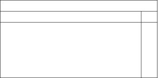
![]()
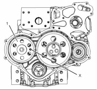
![]()
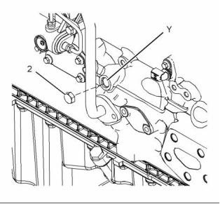
64
KENR9124-01
Testing and Adjusting Section
3. Install Tooling (B) through the hole (X) in the
camshaft gear (1) into the front housing. Use
Tooling (B) in order to lock the camshaft in the
correct position.
i04319681
Fuel Injection Timing - Check
Table 3
Required Tools
Tool
Part Number
21825576
27610291
27610289
T400014
Part Description
Crankshaft Turning Tool
Barring Device Housing
Gear
Qty
1
A
(1)
1
A
(2)
1
B
Timing Pin (Crankshaft)
1
g02337216
Illustration 63
Timing Pin (Fuel Injection
Pump)
C
T400015
1
Typical example
(1) The Crankshaft Turning Tool is used on the front pulley.
(2) This Tool is used in the aperture for the electric starting motor.
2. Install Tooling (C) into hole in adapter plate
at Position (Y). Use Tooling (A) to rotate the
crankshaft until Tooling (C) locates into the slot in
the gear for the fuel injection pump.
NOTICE
Ensure that all adjustments and repairs that are
carried out to the fuel system are performed by
authorized personnel that have the correct train-
ing.
Before beginning ANY work on the fuel system, re-
fer to Operation and Maintenance Manual, “Gen-
eral Hazard Information and High Pressure Fuel
Lines” for safety information.
Refer to Systems Operation, Testing and Adjust-
ing, “Cleanliness of Fuel System Components” for
detailed information on the standards of cleanli-
ness that must be observed during ALL work on
the fuel system.
This procedure must be done before any of the
following:
• Removal of the fuel injection pump.
• The bolts that hold the fuel injection pump to the
front housing are loosened.
g01958182
Illustration 64
Typical example
1. If necessary, install the fuel injection pump. Refer
to Disassembly and Assembly, “Fuel Injection
Pump - Install” for the correct procedure.
3. Remove plug (1) from the cylinder block. If
necessary, use Tooling (A) in order to rotate the
crankshaft until the number one piston is at the
top center position.
Note: The number one piston may be on the
compression stroke or the exhaust stroke.
This document is printed from SPI². Not for RESALE
![]()

![]()
![]()
![]()
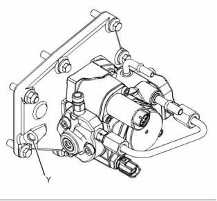
![]()
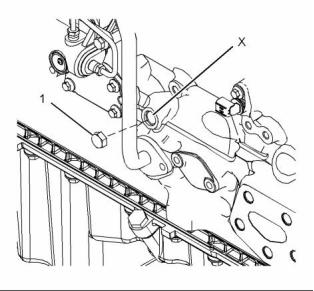
KENR9124-01
65
Testing and Adjusting Section
4. Install Tooling (B) into Hole (X) in the cylinder
block. Use Tooling (B) in order to locate the
crankshaft in the correct position.
3. If fuel quality is still suspected as a possible
cause to problems regarding engine performance,
disconnect the fuel inlet line. Temporarily operate
the engine from a separate source of fuel that
is known to be good. This will determine if the
problem is caused by fuel quality. If fuel quality
is determined to be the problem, drain the
fuel system and replace the fuel filters. Engine
performance can be affected by the following
characteristics:
Note: Do not use excessive force to install Tooling
(B). Do not use Tooling (B) to hold the crankshaft
during repairs.
5. Remove Tooling (C) from the adapter plate.
6. Remove Tooling (B) from the cylinder block.
• Cetane number of the fuel
• Viscosity of the fuel
• Lubricity of the fuel
• Air in the fuel
i04026058
Fuel Quality - Test
Note: Refer to Systems Operation, Testing
and Adjusting, “Cleanliness of Fuel System
Components” for detailed information on the
standards of cleanliness that must be observed
during ALL work on the fuel system.
• Other fuel characteristics
Refer to Operation and Maintenance Manual,
“Fuel Recommendations” for more information on
the cetane number of the fuel.
Ensure that all adjustments and repairs are performed
by authorized personnel that have had the correct
training.
i04081709
Fuel System - Prime
Use the following procedure to test for problems
regarding fuel quality:
1. Determine if water and/or contaminants are
present in the fuel. Check the water separator.
Drain the water separator, if necessary. A full
fuel tank minimizes the potential for overnight
condensation.
Note: Refer to Systems Operation, Testing,
and Adjusting, “Cleanliness of Fuel System
Components” for detailed information on the
standards of cleanliness that must be observed
during ALL work on the fuel system.
Note: A water separator can appear to be full of fuel
when the water separator is full of water.
Ensure that all adjustments and repairs are performed
by authorized personnel that have had the correct
training.
2. Determine if contaminants are present in the
fuel. Remove a sample of fuel from the bottom
of the fuel tank. Visually inspect the fuel sample
for contaminants. The color of the fuel is not
necessarily an indication of fuel quality. However,
fuel that is black, brown, and/or like sludge can
be an indication of the growth of bacteria or oil
contamination. In cold temperatures, cloudy fuel
indicates that the fuel may not be suitable for
operating conditions.
NOTICE
Do not crank the engine continuously for more than
30 seconds. Allow the starting motor to cool for two
minutes before cranking the engine again.
If air enters the fuel system, the air must be purged
from the fuel system before the engine can be
started. Air can enter the fuel system when the
following events occur:
Refer to Operation and Maintenance Manual,
“Fuel Recommendations” for more information.
• The fuel tank is empty or the fuel tank has been
partially drained.
• The low-pressure fuel lines are disconnected.
• A leak exists in the low-pressure fuel system.
• The fuel filter has been replaced.
Use the following procedure in order to remove air
from the fuel system:
This document is printed from SPI². Not for RESALE
![]()
![]()
![]()