English
 Espaol
 Franais
 阿拉伯
阿拉伯 中文
中文 Deutsch
 Italiano
 Português
 日本
日本 韓國(guó)
 български
 hrvatski
 esky
esky Dansk
Dansk Nederlands
 suomi
suomi Ελληνικ
 印度
印度 norsk
norsk Polski
 Roman
Roman русский
 Svenska
Perkins2000車(chē)間維修手冊(cè)供應(yīng)商,Perkins2000車(chē)間維修手冊(cè)技術(shù)價(jià)格規(guī)格咨詢(xún)服務(wù),Perkins2000車(chē)間維修手冊(cè)零配件供應(yīng),Perkins2000車(chē)間維修手冊(cè)售后服務(wù)中心,Perkins2000車(chē)間維修手冊(cè),Perkins2000車(chē)間維修手冊(cè)詳細(xì)的技術(shù)參數(shù),

首頁(yè)
產(chǎn)品展示>Perkins2000車(chē)間維修手冊(cè)
產(chǎn)品中心
美國(guó)強(qiáng)鹿柴油機(jī)維修配件技術(shù)中心
約翰迪爾John Deere柴油機(jī)配件 美國(guó)麥克福斯
卡特彼勒柴油發(fā)動(dòng)機(jī)參數(shù)
沃爾沃發(fā)動(dòng)機(jī)全系參數(shù)
英國(guó)珀金斯原廠(chǎng)配件
珀金斯柴油機(jī)技術(shù)中心
珀金斯發(fā)動(dòng)機(jī)零件查詢(xún)圖冊(cè)
日本三菱柴油機(jī)發(fā)電機(jī)配件
德國(guó)道依茨 韓國(guó)大宇柴油發(fā)動(dòng)機(jī)配件
康明斯全系列柴油發(fā)動(dòng)機(jī)
沃爾沃 MTU 原廠(chǎng)配件銷(xiāo)售中心
瑞典沃爾沃遍達(dá)原裝柴油機(jī)配件
康明斯維修技術(shù)中心
卡特彼勒柴油發(fā)動(dòng)機(jī)原廠(chǎng)配件銷(xiāo)售中心
品牌柴油發(fā)電機(jī)組
康明斯柴油發(fā)動(dòng)機(jī)配件中心
Perkins2000車(chē)間維修手冊(cè)
詳細(xì)描述
Perkins 2000 Series
WORKSHOP MANUAL
6 cylinder diesel engines
for industrial applications
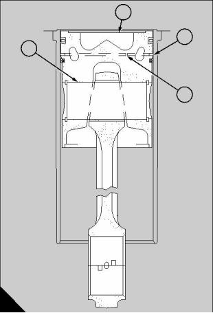
1 Use piston ring pliers, 21825 793, to remove the
rings from the piston.
2 Make a note of the relationship between the
‘FRONT’ marking on the piston and the correlation
marks on the connecting rod.
3 Remove the gudgeon pin circlips and push out the
pin sufficiently to release the piston from the
connecting rod. Keep each assembly together.
3
A
13
To assemble
1 Fit the rings to the piston ensuring that the non-
reversible rings are fitted correctly.
2 Heat the piston to approximately 20°C (68°F). Oil
the small end bushes and assemble the rod to the
piston with the ‘FRONT’ marking on the piston crown
in correct relationship to the correlation marks.
Ensure that the gudgeon pin circlips are correctly
located in their grooves.
3 Set the gaps of the piston rings at equidistant
intervals as shown (A) before the assembly is fitted to
the engine.
Perkins Engines Company Limited
49
This document has been printed from SPI². Not for Resale
![]()
![]()
![]()
![]()
13
Piston and rings
Connecting rod
13-3 To inspect
To inspect
13-4
1 De-carbonise the piston by soaking in a proprietary 1 Crack test the rod assembly electromagnetically
solvent such as ‘Ardrox 691’.
and inspect the bolts for signs of wear or damage.
Renew any components found to be defective.
2 Check the piston for damage or wear. Use a new
piston ring as a guide when checking for wear in the
ring grooves.
2 Check the small end bushes and renew as
necessary, operation 13-5.
3 Crack test the gudgeon pin and check for a push fit 3 Check the alignment of the big and small end bores
in the piston at 20°C (68°F). If the pin is slack in the
piston the assembly should be discarded.
in two planes. Do NOT attempt to correct a bent or
twisted rod.
4 Check the piston rings for damage, scores, wear,
and signs of leakage. Discard the top ring if the
molybdenum shows signs of wear or breaking up, if
necessary, comparing it with a new ring.
5 The spring in the oil control ring gives a radial
pressure of 1035 kN/m² (150 lb/in²) when new and is
identified by a yellow paint marking. Inspect the ring
for wear, and if found to be defective, the ring and
spring together must be renewed.
4 Carefully inspect the bearings for cracks, scores,
wear and embedded foreign material. If there is any
doubt regarding their serviceability the bearings
should be renewed. Always ensure that replacement
bearings are of the correct size and type.
6 Place the rings in turn in an unworn portion of their
own liner to check the ring gaps. Discard any ring
which has a gap exceeding the limits. Piston rings
must be renewed when fitting a new cylinder liner.
50
Perkins Engines Company Limited
This document has been printed from SPI². Not for Resale
![]()
![]()
![]()
![]()
![]()
![]()
13
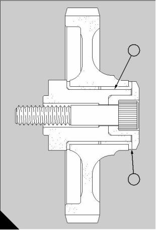
Small end bushes
To renew
13-5
Special tools:
Con-rod bush remover/replacer, 21825 814
For use only on early engines.
Early engines
1 Press out the unserviceable bushes. Remove any
burrs from the eye of the connecting rod and ensure
that the oilway is clear.
A
282
2 New bushes should be drawn in one from each side.
A tool, 21825 814 (A), is available for this purpose.
Ensure that the bushes are correctly fitted with a space
between them of at least 2,5 mm (0.10 in) to form an
oilway.
New engines - engines fitted with wedge-type
connecting rods
1 Press out the unserviceable single small end bush.
Remove any burrs from the eye of the connecting rod
and ensure that the oilway is clear.
2 Press a new bush into the connecting rod, ensuring
that the oil hole is correctly aligned with the hole in the
rod.
Caution: The oil hole in the new bush must be aligned
with the oil hole in the connecting rod to within ±1°.
3 Cut off the protruding edges of the bush and dress
up with a smooth file until flush with the side faces of
the rod.
4 Secure the connecting rod in a boring machine and
bore the bush to the correct diameter:
50,813 to 50,838 mm (2.0005 to 2.0015 in).
Remove any burrs.
Perkins Engines Company Limited
51
This document has been printed from SPI². Not for Resale
![]()
![]()
![]()
![]()
![]()
13
Fits and clearances
2
3
4
1
A
291
Pistons
Gudgeon pin in piston
Bore of piston (A1). . . . . . . . . . . . . . . . . . . . . . . . . . . . . . . . . . . 50,8000 to 50,8025 mm (2.0000 to 2.0001 in)
Gudgeon pin diameter . . . . . . . . . . . . . . . . . . . . . . . . . . . . . . 50,8000 to 50,8064 mm (2.00000 to 2.00025 in)
Gudgeon pin in piston - clearance (new) . . . . . . . . . . . . . . . . -0,0063 to +0,0025 mm (-0.00025 to +0.0001 in)
Top groove in piston
(Wedge shaped for top ring OE 48644)
Diameter over 2,779 mm (0.1094 in) rollers . . . . . . . . . . . . . . . . . 128,981 to 129,184 mm (5.078 to 5.086 in)
Piston clearance at top dead centre
Piston crown (A2) below top face of crankcase. . . . . . . . . . . . . . . . . . . . . 0,28 to 0,38 mm (0.011 to 0.015 in)
(Machine the piston crown to obtain the correct clearance)
52
Perkins Engines Company Limited
This document has been printed from SPI². Not for Resale
![]()
![]()

13
Fits and clearances
2
3
4
1
A
291
Piston rings
Depending on the application, different piston and piston ring combinations are used on the range of 2000
series engines. Use the part number of the piston rings to determine the correct clearances for the piston rings.
Clearances of piston rings in grooves (A3)
Top ring OE 48644 (wedge shaped) . . . . . . . . . . . . . . . . . . . . . . . . . . . . . . . . . . Refer to ring gap dimensions
Second ring OE 48645 (new) . . . . . . . . . . . . . . . . . . . . . . . . . . . . . . . 0,076 to 0,114 mm (0.003 to 0.0045 in)
Maximum permissible worn clearance . . . . . . . . . . . . . . . . . . . . . . . . . . . . . . . . . . . . . . . 0,152 mm (0.006 in)
Oil control ring OE 48646 (new) . . . . . . . . . . . . . . . . . . . . . . . . . . . . . 0,025 to 0,063 mm (0.001 to 0.0025 in)
Maximum permissible worn clearance . . . . . . . . . . . . . . . . . . . . . . . . . . . . . . . . . . . . . . . 0,102 mm (0.004 in)
Clearances of piston rings in grooves (A3)
Top ring OE 50977 (wedge shaped) . . . . . . . . . . . . . . . . . . . . . . . . . . . . . . . . . . Refer to ring gap dimensions
Second ring OE 52517 (new) . . . . . . . . . . . . . . . . . . . . . . . . . . . . . . . 0,076 to 0,113 mm (0.003 to 0.0044 in)
Maximum permissible worn clearance . . . . . . . . . . . . . . . . . . . . . . . . . . . . . . . . . . . . . . . 0,152 mm (0.006 in)
Oil control ring OE 52518 (new) . . . . . . . . . . . . . . . . . . . . . . . . . . . . 0,023 to 0,060 mm (0.0009 to 0.0024 in)
Maximum permissible worn clearance . . . . . . . . . . . . . . . . . . . . . . . . . . . . . . . . . . . . . . . 0,010 mm (0.004 in)
Second ring OE 50978 (new) . . . . . . . . . . . . . . . . . . . . . . . . . . . . . . . 0,076 to 0,113 mm (0.003 to 0.0044 in)
Maximum permissible worn clearance . . . . . . . . . . . . . . . . . . . . . . . . . . . . . . . . . . . . . . . 0,152 mm (0.006 in)
Oil control ring OE 50979 (new) . . . . . . . . . . . . . . . . . . . . . . . . . . . . 0,023 to 0,060 mm (0.0009 to 0.0024 in)
Maximum permissible worn clearance . . . . . . . . . . . . . . . . . . . . . . . . . . . . . . . . . . . . . . . 0,010 mm (0.004 in)
Perkins Engines Company Limited
53
This document has been printed from SPI². Not for Resale
![]()
![]()
13
2
3
4
1
A
291
Piston ring gaps (A4) measured with the ring fitted in a new liner
Top ring OE 48644 (new). . . . . . . . . . . . . . . . . . . . . . . . . . . . . . . . . . . . . . 0,40 to 0,60 mm (0.016 to 0.024 in)
Maximum permissible worn gap . . . . . . . . . . . . . . . . . . . . . . . . . . . . . . . . . . . . . . . . . . . . . 1,52 mm (0.060 in)
Second ring OE 48645 (new). . . . . . . . . . . . . . . . . . . . . . . . . . . . . . . . . . . 0,40 to 0,60 mm (0.016 to 0.024 in)
Maximum permissible worn gap . . . . . . . . . . . . . . . . . . . . . . . . . . . . . . . . . . . . . . . . . . . . . 1,52 mm (0.060 in)
Oil control ring OE 48646 (new). . . . . . . . . . . . . . . . . . . . . . . . . . . . . . . . 0,40 to 0,65 mm (0.016 to 0.0256 in)
Maximum permissible worn gap . . . . . . . . . . . . . . . . . . . . . . . . . . . . . . . . . . . . . . . . . . . . . 1,02 mm (0.040 in)
Top ring OE 50977 (new). . . . . . . . . . . . . . . . . . . . . . . . . . . . . . . . . . . . . . 0,40 to 0,60 mm (0.016 to 0.024 in)
Maximum permissible worn gap . . . . . . . . . . . . . . . . . . . . . . . . . . . . . . . . . . . . . . . . . . . . . 1,52 mm (0.060 in)
Second ring OE 52517 (new). . . . . . . . . . . . . . . . . . . . . . . . . . . . . . . . . . . 0,80 to 1,00 mm (0.031 to 0.039 in)
Maximum permissible worn gap . . . . . . . . . . . . . . . . . . . . . . . . . . . . . . . . . . . . . . . . . . . . . 1,52 mm (0.060 in)
Oil control ring OE 52518 (new). . . . . . . . . . . . . . . . . . . . . . . . . . . . . . . . 0,40 to 0,65 mm (0.016 to 0.0256 in)
Maximum permissible worn gap . . . . . . . . . . . . . . . . . . . . . . . . . . . . . . . . . . . . . . . . . . . . . 1,02 mm (0.040 in)
Second ring OE 50978 (new). . . . . . . . . . . . . . . . . . . . . . . . . . . . . . . . . . . 0,40 to 0,60 mm (0.016 to 0.024 in)
Maximum permissible worn gap . . . . . . . . . . . . . . . . . . . . . . . . . . . . . . . . . . . . . . . . . . . . . 1,52 mm (0.060 in)
Oil control ring OE 50979 (new). . . . . . . . . . . . . . . . . . . . . . . . . . . . . . . . . 0,40 to 0,65 mm (0.016 to 0.026 in)
Maximum permissible worn gap . . . . . . . . . . . . . . . . . . . . . . . . . . . . . . . . . . . . . . . . . . . . . 1,02 mm (0.040 in)
54
Perkins Engines Company Limited
This document has been printed from SPI². Not for Resale
![]()
![]()

13
1
2
3
4
5
A
290
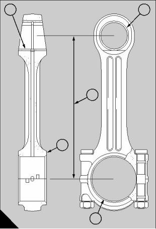
Connecting rods
Gudgeon pin in bush (A1)
Bore of bush . . . . . . . . . . . . . . . . . . . . . . . . . . . . . . . . . . . . . . . . . 50,813 to 50,838 mm (2.0005 to 2.0015 in)
(Bush pressed into position and bored to size)
Diameter of gudgeon pin . . . . . . . . . . . . . . . . . . . . . . . . . . . . 50,8000 to 50,8064 mm (2.00000 to 2.00025 in)
Clearance (new) . . . . . . . . . . . . . . . . . . . . . . . . . . . . . . . . . . . . . . 0,0064 to 0,038 mm (0.00025 to 0.0015 in)
Permissible worn clearance. . . . . . . . . . . . . . . . . . . . . . . . . . . . . . . . . . . . . . . . . . . . . . . 0,067 mm (0.0026 in)
Bush in small end (A2)
Bore in connecting rod. . . . . . . . . . . . . . . . . . . . . . . . . . . . . . . . . . . . 57,137 to 57,15 mm (2.2495 to 2.250 in)
Diameter of bush . . . . . . . . . . . . . . . . . . . . . . . . . . . . . . . . . . . . . . . . 57,277 to 57,328 mm (2.255 to 2.257 in)
Interference fit . . . . . . . . . . . . . . . . . . . . . . . . . . . . . . . . . . . . . . . . . . . . 0,127 to 0,19 mm (0.005 to 0.0075 in)
Alignment of connecting rod (A3)
Parallel alignment between centres. . . . . . . . . . . . . . . . . . . . . . . To be no more than 0,025 mm (0.002 in) out
of parallel over a length of 254 mm (10 inches)
Distance between centres . . . . . . . . . . . . . . . . . . . . . . . . . . . 274,307 to 274,333 mm (10.7995 to 10.8005 in)
End-float of big end (A4)
End-float . . . . . . . . . . . . . . . . . . . . . . . . . . . . . . . . . . . . . . . . . . . . . . . . . 0,076 to 0,20 mm (0.003 to 0.008 in)
Permissible worn end-float . . . . . . . . . . . . . . . . . . . . . . . . . . . . . . . . . . . . . . . . . . . . . . . . 0,305 mm (0.012 in)
Clearance on diameter of big end (A5)
Clearance . . . . . . . . . . . . . . . . . . . . . . . . . . . . . . . . . . . . . . . . . . . . . . . 0,063 to 0,10 mm (0.0025 to 0.004 in)
(Check that crank pin is within the limits of ovality)
Perkins Engines Company Limited
55
This document has been printed from SPI². Not for Resale
![]()
![]()
This document has been printed from SPI². Not for Resale
14
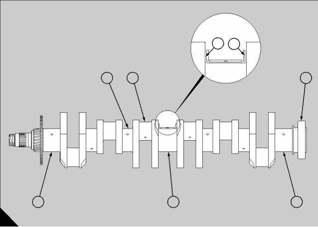
Crankshaft assembly
14
General description
The crankshaft is forged from chrome-molybdenum
steel. It is dynamically balanced, and all bearing
surfaces are nitride-hardened and lapped to size. The
rear flange is machined to form a spigot location for
the flywheel and is drilled to accept the flywheel bolts.
Drillings in the crankshaft permit oil transfer to the
seven main bearings.
A drilling from each journal conveys oil to an adjacent
crankpin, which incorporates an oil reservoir with a
detachable plug. This plug is fitted with an ‘O’ ring and
is secured by a spring clip.
Crankshafts fitted after July 1995, have a new
arrangement of oil passageways which removes the
need for oil reservoirs. These new crankshafts are
therefore not fitted with oil reservoir plugs.
If, during overhaul, the oil reservoir plugs are removed
from the earlier crankshaft, the plugs MUST be
refitted before the engine is run.
Crankshaft end float is controlled by steel-backed
lead bronze thrust washers, fitted either side of the
centre main bearing. The lower half of the washer has
a tang which locates in a slot machined in the bearing
cap.
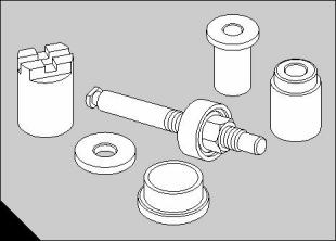
The nose of the crankshaft carries the oil pump drive
gear and the main pinion, and is splined to receive the
hub to which the damper and pulley are attached.
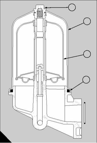
The main crankshaft oil seals are of lip type design.
The rear oil seal is fitted directly into the flywheel
housing and forms a seal around the rear flange of the
crankshaft. For earlier engines the oil seal is carried
in a housing which is bolted to the rear of the
crankcase. The front oil seal is fitted in the wheelcase
and forms a seal around the crankshaft hub. Both
seals are supplied with a plastic insert for fitting
purposes.
Perkins Engines Company Limited
57
This document has been printed from SPI². Not for Resale
![]()
![]()
14
Damper and pulley - early engines
To remove and to fit
14-1
To remove
1 Slacken the belt tensioner pulley and remove the
drive belts.
2 Slacken and remove the bolts which secure the
pulley and damper to the hub.
3 Withdraw the pulley, the hub nut locking plate, the
spacer and the damper, noting the sequence for
refitting.
To fit
1 Assemble the damper, the spacer, the hub nut
locking plate and the pulley to the crankshaft, in the
correct sequence.
2 Fit the sixteen setbolts and spring washers. Tighten
the setbolts evenly to a torque of 41 Nm (30 lbf ft).
3 Refit the drive belts, adjust to the correct tension,
and tighten the belt tensioner pulley.
58
Perkins Engines Company Limited
This document has been printed from SPI². Not for Resale
![]()
![]()
![]()
![]()
14
Damper and pulley - new engines
To remove and to fit
14-2
Engines from build line number 971621 have a new
damper and pulley. The new arrangement does not
include a hub locking plate or a spacer.
The new damper and pulley are fully interchangeable
with those fitted to all earlier engines, but it is NOT
possible to fit the new damper without the new pulley.
To remove
1 Remove the alternator belt. Slacken the tensioner
pulley for the fan belts and remove the fan belts.
2 Slacken and remove the bolts which retain the
pulley and the damper on the crankshaft hub.
3 Remove the pulley and the damper.
To fit
1 Fit the damper and the pulley to the crankshaft. The
pulley fits over the large crankshaft nut. If the bolt
holes in the pulley are not in alignment with those in
the crankshaft hub, remove the pulley, rotate it by one
notch, try it again and if necessary one more time until
the bolt holes are aligned correctly.
Warning! Do NOT loosen the crankshaft nut.
2 Fit the damper and the pulley and fit the 16 bolts
and spring washers. Tighten the bolts to a torque of
41 Nm (30 lbf ft).
3 Fit the drive belts and adjust them to the correct
tension. Tighten securely the tensioner pulley for the
fan belts.
Perkins Engines Company Limited
59
This document has been printed from SPI². Not for Resale
![]()
![]()
![]()
![]()
14
Crankshaft hub and front oil seal
To remove and to fit
14-3
Special tools:
Spanner, 21825 807
To remove
1 Remove the pulley and damper as previously
instructed in this section.
2 Using the spanner, 21825 807, and a suitable
A
152
hammer, unscrew and remove the hub securing nut.
3 Withdraw the hub and front cone.
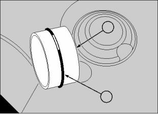
4 Carefully lever out and discard the front oil seal.
To fit
1 Check the crankshaft hub splines and cone for
signs of wear, and renew if necessary.
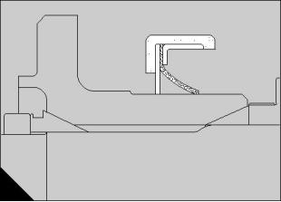
2 Fit a new oil seal to the wheelcase. Ensure that the
seal is positioned correctly, as shown (A).
Note: Each new seal is supplied fitted with a plastic
mandrel for assembly purposes. This mandrel must
NOT be removed until the fitting of the seal is
completed.
3 Apply a light film of clean engine oil to the hub
splines prior to fitting the hub and cone.
4 Check the hub nut threads, lightly oil, and fit the nut
by hand.
5 Tighten the nut to 950 Nm (700 lbf ft) by torque
spanner or, alternatively, by the following method with
the spanner, 21825 807, and a 1,8 kg (4 lb) hammer:
a Use the spanner to tighten the nut as fully as
possible by hand.
b Scribe suitable alignment marks on the hub and
nut and use a hammer to tighten the nut by a
further two flats.
c If difficulties are encountered when fitting the
locking plate, the nut may be tightened by the
minimum amount necessary. It must NOT be
slackened.
6 Fit the pulley and damper, see operation 14-1 or
operation 14-2.
60
Perkins Engines Company Limited
This document has been printed from SPI². Not for Resale
![]()
![]()
![]()
![]()
![]()
14
To fit a new oil seal to a wheelcase removed14-4
from the engine
The plastic mandrel supplied with the seal must NOT
be removed until the fitting of the seal is completed.
Grease, oil or other sealants must NOT be applied to
the seal or housing during assembly.
1 Ensure the seal housing in the wheelcase is free
from oil and other possible debris.
2 Support the wheelcase on a flat horizontal surface
under a hand press, ensuring sufficient clearance is
available to avoid disturbing the plastic mandrel whilst
pressing in the seal.
3 Place the seal at the entrance to the bore with the
part number facing outwards.
4 Cover the seal completely with a flat metal plate
and operate the press until light bottoming of the seal
is felt.
5 Wipe away any excess dry sealant which has been
displaced from the seal outer casing.
6 Do NOT remove the plastic mandrel until the
wheelcase has been fitted to the engine.
Perkins Engines Company Limited
61
This document has been printed from SPI². Not for Resale
![]()
![]()
![]()
14
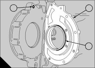
Rear oil seal
To remove and to fit
14-5
1
2
Special tools:
Oil seal tool, 27610 007
To remove
1 Drain the engine oil and remove the flywheel,
A
operation 22-1.
35
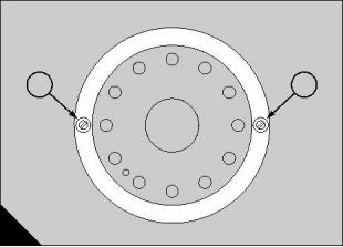
2 Use a centre punch to make two holes in the edge
4 Remove the complete tool. The tool should be kept
of the seal at diametrically opposite positions (A1 and
assembled to protect the guide part.
5 Fit the flywheel, operation 22-1.
3
A2). Drill two holes, of 5 mm ( / in) diameter, in the
16
seal at the positions shown (A1 and A2).
3 Select two suitable self-tapping screws, complete
with plain washers, and fit the screws to the drilled
holes. Leave a small space between the face of the
seal and the plain washers. Use two screwdrivers, as
levers, between the plain washers and the flywheel
housing (oil seal housing on early engines) to remove
the oil seal.
4 Clean the bore of the flywheel housing, or oil seal
housing, which was in contact with the old seal.
To fit
Ensure that the crankshaft and the bore of the
flywheel housing are clean and free from grease.
Caution: Check that the part number of the new seal
is the correct one for the engine.
1 Ensure that the flywheel location dowel is fitted to
the crankshaft. Fit the guide part of the special tool,
27610 007, onto the end of the crankshaft and secure
it with the four bolts. Take care not to damage the fine
edge of the guide during fitting.
2 Before the oil seal is fitted, check the guide and the
crankshaft again for dirt or for a rough surface finish
which could damage the lip of the oil seal. Remove
and discard the yellow inner sleeve from the new oil
seal and fit the seal onto the guide. The lip of the seal
must be toward the crankcase.
Caution: Do NOT apply oil or grease to the oil seal
to assist the operation. There is a dry lubricant on the
contact face of a new seal for this purpose.
3 Slide the collar part of the tool onto the guide until
the face of the collar is against the outer face of the oil
seal. Lubricate lightly the thread of the stud and also
the thrust washer. Fit the nut and washer to retain the
collar. Rotate the nut until the seal is pressed fully into
the flywheel housing or oil seal housing for earlier
engines.
62
Perkins Engines Company Limited
This document has been printed from SPI². Not for Resale
![]()
![]()
![]()
![]()
![]()
14
18 Remove the main bearing caps, if necessary
using the puller, 21825 806, and remove the lower
half main bearing shells from the caps.
Crankshaft
To remove and to fit
14-6
19 Using suitable lifting equipment, lift out the
crankshaft and remove the upper half of the main
bearing shells and thrust washers.
Special tools:
To fit
Engine build stand, 21825 993
Puller, 21825 806
1 Lightly oil the upper halves of the main bearing
shells and fit them to the crankcase.
2 Carefully lower the crankshaft into position.
To remove
3 Fit the main bearing caps as given in operation
16-2, paragraphs 3 and 4. Check that the
crankshaft rotates freely. Lever the crankshaft to
the extremes in each direction and measure the
end float. Limits are 0,127 to 0,33 mm (0.005 to
0.013 in).
4 Withdraw each piston and connecting rod assembly
from its bore and fit the upper half of the big end
bearing to the connecting rod. Ensure that the
location tang is correctly seated. Lubricate the
bearing with clean engine oil and guide the
connecting rod carefully onto the crank pin. Fit the
lower half of the bearing into the big end cap, ensuring
correct location, and lubricate with clean engine oil.
Ensure that the flats on the big end bolts are correctly
located against the flats on the connecting rod. Fit the
bearing cap with the correlation marks aligned and
tighten the lightly oiled nuts to a torque of 217 Nm
(160 lbf ft).
1 Drain the engine lubricating oil and coolant whilst
the engine is still installed.
2 Remove the unit and fit it to the engine build stand,
21825 993. See operation 16-1.
3 Remove the sump and oil pump, operation 19-3
and operation 19-4.
4 Remove the coolant pump, operation 21-5 and the
thermostat housing/coolant rail assembly.
5 If fitted, remove the compressor, operation 24-1.
6 Remove the fuel injection pump, operation 20-10.
7 Remove the starter motor, operation 23-3.
8 Remove the alternator, operation 23-2.
9 Remove the flywheel housing, operation 22-3.
10 If fitted, remove the crankshaft rear seal housing.
11 Remove the crankshaft hub and damper
assembly, operation 14-3 and operation 14-1 or
operation 14-2.
5 Fit the backplate, complete with a new gasket and,
where necessary, the fuel pump adapter plate,
complete with new ‘O’ ring seals.
6 Turn the engine until No.1 piston is at the TDC
position. Fit the camshaft and idler gears with the
timing marks correctly aligned - see section 16.
12 Remove the wheelcase, operation 15-1.
13 Unscrew the idler gear retaining bolt and withdraw
the gear and thrust plate.
14 Remove the camshaft gear or, for engines with an
integral gear, remove the camshaft, operation 16-8.
7 Fit the wheelcase.
15 If fitted, remove the fuel pump adapter plate and
discard the ‘O’ rings. Remove the wheelcase
backplate and discard the gasket.
16 Disconnect the connecting rods from the
crankshaft. Ensure that the caps and shell bearings
are retained with their respective rods.
8 Fit the crankshaft hub and damper assembly,
operation 14-3 and operation 14-1 or operation 14-2.
9 For early 2000 series engines, fit the crankshaft
rear seal housing.
10 Fit the flywheel housing, operation 22-3.
11 Fit the alternator, operation 23-2.
12 Fit the starter motor, operation 23-3.
13 Fit the fuel injection pump, operation 20-10.
14 If necessary, fit the compressor, operation 24-1.
17 Slide the piston and connecting rod assemblies
into the bores until they are clear of the crankshaft.
Perkins Engines Company Limited
63
This document has been printed from SPI². Not for Resale
![]()
![]()
![]()
![]()
![]()
14
15 Fit the coolant pump, operation 21-5 and the
thermostat housing/coolant rail assembly.
16 Fit the oil pump and sump, operation 19-4 and
operation 19-3.
17 Remove the engine from the build stand,
operation 16-1.
18 Refill with clean engine oil of the correct grade and
specification.
19 Fill the coolant system to the correct level with the
approved coolant mixture.
To inspect
14-7
1 Thoroughly clean the assembly.
2 Inspect the pinion and oil pump drive gear
assembly for wear and damage.
3 Where relevant, extract all the oil reservoir plugs:
tap each plug in slightly, remove the retaining clip and
screw in a suitable bolt to withdraw the plug.
4 Clean all the components with special attention to
the crankshaft oilways.
5 Perform a crack test on the shaft, pinion and oil
pump drive gear, preferably using the
electromagnetic process. Renew as necessary.
6 Where relevant, refit the oil reservoir plugs,
complete with new ‘O’ rings, as follows: Oil the bores,
press in the plugs, fit the retaining clips and pull the
plugs back against the retaining clips.
If necessary, it is possible for the crankshaft to be
reground. Re-grinding is permissible in four stages,
each of 0,25 mm (0.010 in) on the diameter.
Caution: The crankshaft MUST be re-nitrided if it is
re-ground by more than 0,25mm (0.010 in).
Should the crankshaft be re-ground several times, re-
nitriding will be necessary at:
a Minus 0,51 mm (0.020 in)
and
b Minus 1,02 mm (0.040 in)
For further details about crankshaft re-grinding,
please contact the Service Department at Perkins
Engines Company Limited, Shrewsbury.
64
Perkins Engines Company Limited
This document has been printed from SPI². Not for Resale
![]()
![]()
![]()
![]()
14
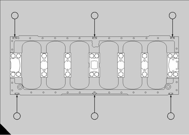
Fits and clearances
Crankshaft journals
Diameter (A1) . . . . . . . . . . . . . . . . . . . . . . . . . . . . . . . . . . . . . . 99,0473 to 99,0727 mm (3.8995 to 3.9005 in)
Permissible worn dimensions . . . . . . . . . . . . . . . . . . . . . . . . . . . . . . . . . . . . . . . . . . . . 98,9838 mm (3.897 in)
Ovality - permissible worn dimensions . . . . . . . . . . . . . . . . . . . . . . . . . . . . . . . . . . . . . . . 0,076 mm (0.003 in)
Journals in main bearings - clearance. . . . . . . . . . . . . . . . . . . . . . . 0,0127 to 0,089 mm (0.0005 to 0.0035 in)
Crank pins
Diameter (A2) . . . . . . . . . . . . . . . . . . . . . . . . . . . . . . . . . . . . . . 82,5348 to 82,5373 mm (3.2494 to 3.2495 in)
Diameter - permissible worn dimensions. . . . . . . . . . . . . . . . . . . . . . . . . . . . . . . . . . . 82,4611 mm (3.2465 in)
Ovality - permissible worn dimensions . . . . . . . . . . . . . . . . . . . . . . . . . . . . . . . . . . . . . . . 0,076 mm (0.003 in)
Deflection of crankshaft
Deflection of crankshaft (A7) when it is held on
‘V’ blocks under numbers 1 and 7 main journals (A6). . . . . . . . . . . . . . . . . . . . . . . . . . . . 0,030 mm (0.012 in)
(The deflection must be progressive from the outer main journals to the centre main journal)
End-float of crankshaft
Width between crankshaft webs of central journal (A3) . . . . . . . . . . 80,645 to 80,696 mm (3.175 to 3.177 in)
Width of centre bearing and thrust washers (A4) . . . . . . . . . . . . . . . 80,315 to 80,467 mm (3.162 to 3.168 in)
Clearance (new) . . . . . . . . . . . . . . . . . . . . . . . . . . . . . . . . . . . . . . . . . . 0,178 to 0,381 mm (0.007 to 0.015 in)
Permissible worn clearance. . . . . . . . . . . . . . . . . . . . . . . . . . . . . . . . . . . . . . . . . . . . . . . . . 0,51 mm (0.020 in)
Flywheel on crankshaft
Diameter of crankshaft (A5). . . . . . . . . . . . . . . . . . . . . . . . . . . . . . 107,899 to 107,925 mm (4.248 to 4.249 in)
Bore of flywheel. . . . . . . . . . . . . . . . . . . . . . . . . . . . . . . . . . . . . . . . 107,95 to 107,975 mm (4.250 to 4.251 in)
Clearance (new) . . . . . . . . . . . . . . . . . . . . . . . . . . . . . . . . . . . . . . . . . . 0,025 to 0,076 mm (0.001 to 0.003 in)
3
4
1
2
5
6
7
6
A
293
Perkins Engines Company Limited
65
This document has been printed from SPI². Not for Resale
![]()
![]()
This document has been printed from SPI². Not for Resale
15
Wheelcase and drive assembly
15
General description
The wheelcase assembly of the new 2000 series
engine consists of an aluminium wheelcase and a
cast iron backplate. For earlier engines, the backplate
is manufactured from aluminium. The assembly is
situated at the front end of the crankcase and houses
the engine gear train. The backplate is located on the
crankcase by dowels and is secured by close fitting
bolts. This ensures the correct positioning of the front
seal in relation to the crankshaft.
A steel oil transfer tube is fitted between the backplate
and the front end of the main oil gallery in the
crankcase. Lubricating oil is supplied through this
tube and through drillings in the backplate to the fuel
injection pump.
The wheelcase provides mounting points for the
coolant pump, alternator and belt tensioner bracket.
The backplate houses the radiator by-pass tube and
provides mounting points for the compressor and fuel
injection pump.
The gears of new 2000 series engines have a
different gear tooth design and are not
interchangeable with those fitted to earlier engines.
The idler axle fitted to new 2000 engines does not
require adjustment.
Perkins Engines Company Limited
67
This document has been printed from SPI². Not for Resale
![]()
![]()
15
Wheelcase
Backplate
To remove and to fit
15-1 To remove and to fit
15-2
To remove
To remove
1 Drain the engine coolant.
1 Remove the wheelcase, operation 15-1.
2 Remove the fuel injection pump assembly,
2 Remove the following components:
a (a) Sump - see operation 19-3.
b Alternator - see operation 23-2.
c Belt tensioner bracket.
d Crankshaft hub - see operation 14-3.
e Coolant pump - see operation 21-5.
f Compressor (if fitted) - see operation 24-1.
operation 20-10.
3 Remove the coolant rail, thermostat housing and
the radiator by-pass tube from the top of the
backplate.
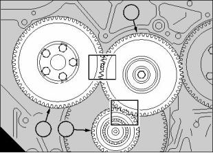
4 Turn the engine until No.1 piston is at TDC with the
relevant mark on the flywheel aligned with the timing
pointer in the flywheel housing. The timing marks on
the camshaft and crankshaft gears should now be
facing the idler gear axle, and the mark on the front
end of the crankshaft at the 12 o’clock position.
5 Bend back the tabs on the camshaft gear locking
plate and slacken the retaining bolts. The camshafts
of certain engines have an integral gear; for these
engines the camshaft must be removed, operation
16-8.
3 Remove the wheelcase retaining bolts and
withdraw the casing.
4 Discard all gaskets and clean the joint faces.
To fit
1 Renew all gaskets.
2 Fit the wheelcase, complete with a new gasket.
3 Fit the components removed in paragraph 2 of the
6 Remove the idler gear retaining bolt and withdraw
removal sequence.
the gear and thrust washer.
4 Refill the coolant system.
7 For engines with removable camshaft gears:
Unscrew the camshaft gear retaining bolts and
remove the gear and lockplate, then remove the
camshaft thrust plate.
8 If fitted, remove the fuel pump adaptor housing from
the backplate and discard the ‘O’ rings.
9 Unscrew the three backplate retaining bolts and
carefully tap the plate free from the dowels.
10 Discard the gasket and clean the joint faces.
11 Withdraw the oil transfer tube from the backplate
and discard the ‘O’ ring.
68
Perkins Engines Company Limited
This document has been printed from SPI². Not for Resale
![]()
![]()
![]()
![]()
![]()
![]()
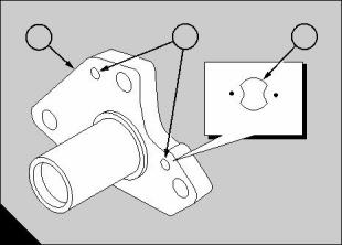
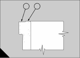
15
To fit
1 Fit the oil transfer tube (A1) to the backplate,
complete with a new ‘O’ ring (A2).
1
2 Fit a new gasket over the two dowels in the front of
the crankcase, fit the backplate and secure with the
three bolts.
3 Fit the camshaft thrust washer and tighten the
setscrews evenly to a torque of 54 Nm (40 lbf ft).
4 Fit the camshaft gear (B1), locating it on the roll pin
in the end of the camshaft. The bolt holes are offset
and will only align in one position. Use a new locking
washer (B5) and fit the bolts (B6) finger tight only at
this stage.
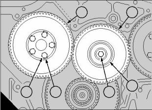
5 Slide the idler gear (B2) on to its axle, with the
timing marks aligned with the corresponding marks on
the camshaft and crankshaft gears as shown (C).
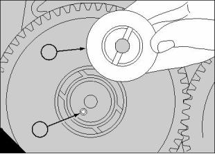
6 Fit the idler gear thrust plate (B3) and securing bolt
(B4). Ensure that the slot in the plate (D1) is correctly
located on the roll pin (D2), then tighten the bolt to a
torque of 61 Nm (45 lbf ft).
7 Tighten the camshaft gear retaining bolts to a
torque of 61 Nm (45 lbf ft), and bend over the locking
plate tabs to secure. Ensure that the tabs are bent
fully against the flats of the bolts heads.
2
A
B
C
D
285
1
2
3
6
5
4
Continued
286
1
3
2
295
1
2
287
Perkins Engines Company Limited
69
This document has been printed from SPI². Not for Resale
![]()
![]()

15
8 For early engines: fit the fuel pump adaptor (A2)
and renew the two ‘O’ ring seals (A1 and A3).
9 Fit the fuel injection pump, operation 20-10.
10 Fit the radiator by-pass tube, thermostat housing
and coolant rail, renewing all gaskets and ‘O’ rings
seals.
1
2
3
11 Fit the wheelcase, operation 15-1.
A
288
70
Perkins Engines Company Limited
This document has been printed from SPI². Not for Resale
![]()
![]()
15
Camshaft gear - bolt-on type
1
To remove and to fit
15-3
To remove
1 Remove the wheelcase, operation 15-1.
2 Turn the engine until No.1 piston is at TDC with the
relevant mark on the flywheel aligned with the timing
pointer in the flywheel housing. The timing marks on
the camshaft and crankshaft gears should now be
facing the idler gear axle as shown (A), and the mark
on the front end of the crankshaft at the 12 o’clock
position.
3
2
A
295
3 Remove the idler gear (A1).
4 If fitted, bend back the locking plate tabs, remove
the retaining bolts and carefully lever off the camshaft
gear (A3).
5 Inspect the gear for worn or damaged teeth and
renew if necessary.
6 Do not turn the engine from its present position.
To fit
1 Fit and secure the camshaft gear (A3) to the
camshaft with the timing mark aligned with the
corresponding marks on the idler gear (A1).
2 Fit the idler gear.
3 Check that the gear backlash is within limits. Refer
to Fits and clearances on page 77. If the backlash is
not within the limits, the position of the idler gear axle
may need to be adjusted, see operation 15-7.
4 Fit the locking plate, if one was previously fitted, fit
the retaining bolts, tighten them to a torque of 61 Nm
(45 lbf ft) and bend up the tabs on the locking plate.
Note: It has been found that the locking plate for the
camshaft gear is no longer required and therefore will
not be fitted to engines manufactured after August
1998.
5 Fit the wheelcase, operation 15-1.
Perkins Engines Company Limited
71
This document has been printed from SPI². Not for Resale
![]()
![]()
![]()
![]()
 <, IMG src="/Editor/uploadfile/20161029085610667.png" width=2 height=2>
15
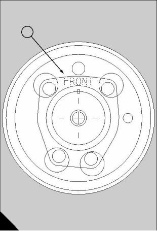
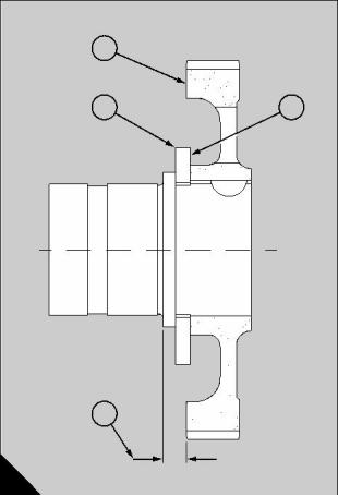
Camshaft gear - integral type
To remove and to fit
15-4
1
To remove
To remove the camshaft gear from this type of
camshaft, the camshaft must first be removed from
the engine.
1 Remove the cam followers, operation 16-6.
2 Remove the idler gear, operation 15-6.
3 Remove the camshaft, operation 16-8.
4 Place the camshaft in a hydraulic press with the
camshaft gear uppermost. Support the gear under the
thrust plate with suitable packing, such as vee blocks.
Carefully press the camshaft from the gear and
remove the thrust plate and the key.
Caution: Do not damage the camshaft during this
operation.
To fit
1 Support the camshaft in a suitable press. Fit the
thrust plate to the camshaft. Ensure that the plate is
fitted with the words ‘FRONT’ (A1) uppermost, away
from the cams.
A
2 Insert a new key in the camshaft keyway.
142
o
3 Heat the gear in a pre-heated oven at 300 C for a
minimum of 15 minutes.
Warning! Protective gloves and overalls must be
2
1
used when handling the heated camshaft gear.
4 Place the gear on the camshaft while still hot and
press it onto the camshaft until the distance between
the rear face of the gear and the rear face of the
camshaft flange (B4) is 11,54 mm (0.4545 in).
3
5 Fit the camshaft, operation 16-8.
4
B
143
72
Perkins Engines Company Limited
This document has been printed from SPI². Not for Resale
![]()
![]()
![]()
![]()
15
To inspect
15-5
1 Inspect the camshaft gear journal for burrs or other
damage. If the damage cannot be removed by the use
of a fine grade of emery cloth, renew the camshaft.
Measure the outside diameter of the journal. It must
be between 65,1637 and 65,1815 mm (2.5655 and
2.5662 in). If it is beyond these limits the camshaft
must be renewed.
2 Inspect the bore of the gear for burrs or other
damage. If the damage cannot be removed by the use
of a fine grade of emery cloth, renew the gear.
Measure the diameter of the gear bore. It must be
between 65,0875 and 65,1078 mm (2.5625 and
2.5633 in). If it is beyond these limits the gear must be
renewed.
Perkins Engines Company Limited
73
This document has been printed from SPI². Not for Resale
![]()
![]()
![]()
15
Idler gear
1
To remove and to fit
15-6
To remove
1 Remove the wheelcase, operation 15-1.
2 Turn the engine until No.1 piston is at TDC with the
relevant mark on the flywheel aligned with the timing
pointer in the flywheel housing. The timing marks on
the camshaft and crankshaft gears (A3 and A2)
should now be facing the axle of the idler gear (A1),
and the mark on the front end of the crankshaft at the
12 o’clock position.
3
2
A
295
3 Check and note the end float of the idler gear.
4 Check the gear for excessive play on the axle.
5 Remove the securing bolt and thrust plate.
6 Withdraw the gear and check for worn or damaged
teeth.
7 Do not turn the engine from its present position.
To fit
1 Slide the gear onto the axle, with the timing marks
aligned with the relevant markings on the camshaft
and crankshaft gears.
2 For new 2000 series engines: Fit the idler gear
thrust plate and securing bolt. Tighten the bolt to a
torque of 300 Nm (220 lbf ft). Check that the end
float is within these limits: 0,10 to 0,25 mm (0.004
to 0.010 in). If it is outside the limits, the assembly
of the idler gear and bushes must be renewed.
For earlier 2000 series engines, fit the idler gear thrust
plate and securing bolt. Ensure that the slot in the plate
is correctly located on the roll pin before tightening the
bolt. Tighten the bolt to a torque of 61 Nm (45 lbf ft).
Check that the end float is within these limits: 0,051 to
0,20 mm (0.002 to 0.008 in). If it is outside the limits,
the assembly of the idler gear and bushes must be
renewed.
3 Check the backlash of the idler gear, see Fits and
clearances on page 77. If a new gear has been fitted,
the position of the idler gear axle may require
adjustment to obtain the correct backlash
dimensions. Refer to page 76. This operation does
NOT apply to new 2000 series engines.
4 Fit the wheelcase,operation 15-1.
74
Perkins Engines Company Limited
This document has been printed from SPI². Not for Resale
![]()
![]()
![]()
![]()

15
To set the gear backlash
15-7
Special tools:
Reaming jig, idler gear axle, 21825 999
Note: This operation is NOT applicable to New 2000
series engines.
The backlash of the timing gears is set by the position
of the idler gear axle. If, during an overhaul, a new
idler gear, a new idler gear axle or a new crankcase is
used, the correct position for the idler gear can
change and effect the backlash setting of the gears.
To obtain the position that will give the correct
backlash settings for the idler gear, the position of the
dowel holes may have to change. To do this, the
dowel holes must be reamed to a larger size by 0,38
mm (0.015 in), this will give them a diameter of 8,33
mm (0.328 in). If this operation has been done before,
they may have to be reamed by a further 0,38 mm
(0.015 in) to a finished size of 8,73 mm (0.3437 in).
According to the size of the dowels which are to be
fitted, a selection of these location pins and reamers
will be necessary:
Dowel size 8,33mm (0.32in) oversize
Dowel part number:
Location pin:
Reamer:
OE51709/1
21825 830
21825 833
21825 831
Location pin:
Dowel size 8,73mm (0.343in) oversize
Dowel part number: OE51709/2
Location pin:
Reamer:
Location pin:
21825 831
21825 834
21825 832
To fit a new idler gear to an existent crankcase
Dowel part number: OE51385
Location pin
Reamer
21825 829
21825 835
Continued
Perkins Engines Company Limited
75
This document has been printed from SPI². Not for Resale
![]()
![]()
![]()
![]()
15
To adjust the backlash of the timing gears
If the crankcase is to have its original idler gear and
idler gear axle fitted, they should be fitted with the
original dowels and then the backlash must be
checked. The backlash limits are:
1
2
3
Between the idler gear and the drive gear for the fuel
injection pump (FIP):
0,05 to 0,15 mm (0.002 to 0.006 in).
Between the idler gear and the camshaft gear:
0,05 to 0,15 mm (0.002 to 0.006 in).
Between the idler gear and the crankshaft gear:
0,15 to 0,40 mm (0.006 to 0.010 in).
A
02
If these clearances cannot be obtained, use the
procedure which follows:
1 The camshaft gear and the crankshaft gear must be
fitted and the FIP drive gear must be fitted, but without
its bolts at this time.
2 Fit the idler gear axle (A1) without the dowels, fit
spring washers to the bolts and tighten the bolts
lightly.
3 Fit the gear and check the backlash at four equally
spaced points on its circumference between the
gears of the camshaft and the crankshaft.
4 Adjust the position of the idler gear axle to achieve
a backlash of 0,05 to 0,15 mm (0.002 to 0.006 in)
between the idler gear and the camshaft gear and
also between the idler gear and the FIP drive gear.
And ensure that the backlash between the idler gear
and the crankshaft gear is between 0,15 and 0,25 mm
(0.006 and 0.010 in).
5 Remove carefully the idler gear, ensure that the
idler gear axle is not disturbed; tighten the bolts of the
idler gear axle to a torque of 61 Nm (45 lbf ft).
Caution: Ensure that the correct tools are used for
the size of dowels to be fitted.
6 Fit the reaming jig, 21825 999, over the idler gear
axle, fit the relevant location pin into one of the dowel
holes (A2) and use the relevant reamer in the other
dowel hole to ream the other hole in the crankcase to
the next relevant size.
7 Fit the relevant locating pin to the dowel hole and
remove the other locating pin. Ream the second
dowel hole with the same reamer.
8 Remove the locating pin and the reaming jig.
Ensure that the dowel holes are clean. Fit new dowels
of the correct size.
9 Use a centre punch to distort the dowel holes
similar to that shown (A3).
10 Fit the idler gear, operation 15-6.
76
Perkins Engines Company Limited
This document has been printed from SPI². Not for Resale
![]()
![]()
15
Fits and clearances
1
2
A
314
Idler gear (A)
Bore of bush when fitted and machined (A1) . . . . . . . . . . . . . . . . . . 51,765 to 51,816 mm (2.038 to 2.040 in)
Axle diameter. . . . . . . . . . . . . . . . . . . . . . . . . . . . . . . . . . . . . . . . . . . 41,2850 to 41,2877 (1.6250 to 1.6255 in)
End-float - new 2000 Series (A2) . . . . . . . . . . . . . . . . . . . . . . . . . . . . . 0,010 to 0,254 mm (0.004 to 0.010 in)
End-float - earlier engines . . . . . . . . . . . . . . . . . . . . . . . . . . . . . . . . . . . . . 0,51 to 0,20 mm (0.002 to 0.008 in)
Gear train
Backlash - new 2000 Series . . . . . . . . . . . . . . . . . . . . . . . . . . . . . . . . . . . . . . . 0,15 to 0,25 (0.006 to 0.010 in)
Permissible worn limit . . . . . . . . . . . . . . . . . . . . . . . . . . . . . . . . . . . . . . . . . . . . . . . . . . . . . 0,38 mm (0.015 in)
Backlash - earlier engines . . . . . . . . . . . . . . . . . . . . . . . . . . . . . . . . . . . . . . . 0,051 to 0,152 (0.002 to 0.006 in)
Permissible worn dimension . . . . . . . . . . . . . . . . . . . . . . . . . . . . . . . . . . . . . . . . . . . . . . . . . . . . 0,20 (0.008 in)
Oil pump drive gear
Backlash - new 2000 Series . . . . . . . . . . . . . . . . . . . . . . . . . . . . . . . . . . . 0,15 to 0,25 mm (0.006 to 0.010 in)
Permissible worn limit . . . . . . . . . . . . . . . . . . . . . . . . . . . . . . . . . . . . . . . . . . . . . . . . . . . . . 0,38 mm (0.015 in)
Backlash - earlier engines . . . . . . . . . . . . . . . . . . . . . . . . . . . . . . . . . . . 0,102 to 0,254 mm (0.004 to 0.010 in)
Permissible worn limit . . . . . . . . . . . . . . . . . . . . . . . . . . . . . . . . . . . . . . . . . . . . . . . . . . . . 0,305 mm (0.012 in)
Perkins Engines Company Limited
77
This document has been printed from SPI². Not for Resale
![]()
![]()
This document has been printed from SPI². Not for Resale
16
Cylinder block assembly
16
General description
The crankcase is a single unit cast in high grade
nickel-chrome iron and comprises the crank chamber
and the cylinder block. The crank chamber extends
below the crankshaft line to ensure rigidity. Lateral
bolts to the front, centre and rear main bearing caps
provide additional stiffness.
Five transverse webs within the crankcase provide
support for the crankshaft and camshaft. The
crankshaft is carried in seven bearings, secured by
removable caps and fitted with thrust washers at the
centre bearing.
The camshaft has seven journals. On all engines prior
to build line number 79339 the camshaft runs in
bearing surfaces machined in the crankcase parent
metal. Industrial engines, from build line number
79339, have a bush fitted to the front journal with the
six remaining journals running in bearing surfaces
machined in the crankcase parent metal.
The low-mounted camshaft is gear driven from the
front of the crankshaft through an idler gear. It is
drilled through its complete length to form an oil
gallery and runs in bearings or bearing surfaces
machined in the crankcase.
Oil is transferred from the centre bearing to lubricate
the remaining six camshaft journals and certain other
components.
The drive gear is located on the shaft by a single
dowel and retained by five setbolts/capscrews and a
locking plate. For certain early engines, the drive gear
is pressed onto the camshaft and is located by a
woodruff key.
Slip-fit wet-type cylinder liners manufactured from
cast iron and which have been induction hardened
are used. The liner bore is honed and carbide
finished, which results in a matt surface.
Caution: If a used liner is to be refitted to an engine,
it is vital that NO re-honing or de-glazing of the bore is
undertaken.
The top of the liner is flanged and forms a coolant seal
with the counterbore seat in the crankcase top face.
Three grooves are machined into the skirt of the liner
to accept three composition sealing rings.
Perkins Engines Company Limited
79
This document has been printed from SPI². Not for Resale
![]()
![]()
16
Crankcase
14 Fit the mounting brackets to the crankcase. Using
a crane and the lifting beam, 21825 821, support the
crankcase, remove the transportation stands and fit
the crankcase to the build stand, 21825 993.
To fit to and to remove from a
build stand
16-1
To remove from a build stand
1 Fit the lift adaptor, 21825 821, to the engine, use a
suitable hoist to remove the engine from the build
stand and support it with transportation feet.
2 Fit the oil cooler assembly and its coolant pipes,
secure pipes with hoses and hose clips. Fit the
connecting pipework between the sump, oil cooler
and crankcase and fit the compressor oil feed pipe.
Special tools:
Strap wrench, 21825 825
Lift adaptor for engine, 21825 821
Build stand - engine, 21825 993
To fit to a build stand
3 Fit the engine stop solenoid, refer to section 23 for
To obtain access to the crankcase and further main
components, the engine must be disconnected from
its driven unit and fitted in a build stand. Instructions
to disconnect the driven unit are to be found in the
publication of the relevant manufacturer. To fit the
engine to a build stand proceed as follows:
setting details.
4 Fit new oil filter canisters as detailed in section 4 of
the User’s Handbook, TSD 3215.
5 Fit the oil by-pass filter together with all the relevant
pipework.
Warning! Fuel and oil pipes MUST be inspected for
1 Disconnect the batteries.
cracks or damage before they are fitted to the engine.
2 Close the valves and disconnect the pipes for the
6 Fit the fan, operation 21-2.
7 Connect the exhaust pipes.
8 Fit the radiator, operation 21-1.
fuel supply and the fuel return.
3 Drain the coolant system (refer to the User’s
Handbook TSD 3215), remove the radiator, operation
21-1, and the relevant coolant pipes and air ducts.
9 Fit the air cleaner assembly and connect the
Warning! Remove carefully the radiator filler cap as
ducting to the turbocharger.
the system may be under pressure.
10 Set the fuel injection pump timing, operation 17-2.
4 Drain the lubricating oil from the engine by the
11 Fill the lubrication system to the correct level with
clean engine lubricating oil, see User’s Handbook
TSD 3215.
removal of the drain plugs from the base of the sump.
5 Remove the fan, operation 21-2.
12 Fill the coolant system to the correct level, see
6 Remove the air cleaner assembly and the ducting
User’s Handbook TSD 3215.
to the turbocharger.
13 Connect the fuel supply.
14 Connect the batteries.
15 Eliminate air from the fuel system, operation 20-11.
7 If a compressor is fitted, remove the compressor air
filter and associated pipework. Disconnect the
coolant and oil pipework and remove the compressor.
8 Remove the turbocharger exhaust outlet pipe and,
where applicable, the diffuser. Prior to removal, scribe
alignment marks to ensure correct orientation on
reassembly.
9 Remove the alternator and drive belt.
10 Slacken the belt tensioner and remove the belts
and the tensioner assembly.
11 Use the filter wrench, 21825 825, to remove the oil
filter canisters. Disconnect all relevant pipework and
remove the oil cooler and, if fitted, the oil bypass filter.
12 Remove the turbocharger(s), complete with the oil
supply and drain pipework.
13 Remove the oil filler and the dipstick tube
assemblies.
80
Perkins Engines Company Limited
This document has been printed from SPI². Not for Resale
![]()
![]()
![]()
![]()
![]()
16
Take care not to damage the rocker oil feed studs.
Remove the coolant bobbins, head gaskets, roll pins
and oil feed studs; a special tool, 21825 800, is
available for bobbin removal.
To dismantle and to assemble
16-2
Special tools:
Cylinder head lifting bar, 21825 816
Bobbin removal tool, 21825 800
Flywheel lifting bracket, 21825 817
Bearing cap removal tool, 21825 806
Engine build stand, 21825 993
Lapping tool. 21825 902
Piston replacer sleeve, 21825 784
Dial gauge, 21825 782
Torque angle gauge, 21825 924
Sump guide studs, 21825 812
Flywheel guide studs, 21825 802
Spanner, 21825 807
12 Remove the starter motor and solenoid assembly,
operation 23-3.
13 Remove the tappet cover, gasket, baffle plate and
the rocker oil feed pipe. Lift out the cam followers. The
cam followers must be stored in the correct sequence
to ensure that they are fitted to their original positions
when the engine is assembled.
14 Remove the flywheel, operation 22-1, use the
lifting bracket 21825 817. Remove the flywheel
housing, operation 22-3.
15 Rotate the build stand until the sump is uppermost
and remove the sump.
16 Remove the wheelcase, operation 15-1.
17 Remove the oil transfer pipes, the connections
and the suction intake assembly. Remove the oil
pump complete with drive gear and shims.
To dismantle
1 Fit the assembly of the engine to a build stand,
Note: Shims are not fitted to the oil pumps of new
operation 16-1.
2000 series engines.
It is recommended that small items (for example: low
pressure fuel pipes, clips, brackets, etc.) are labelled,
to indicate their location and purpose, and are stored
with the relevant engine parts.
18 Remove the rear end oil seal housing - not fitted
to new 2000 series engines.
19 Disconnect and remove the stop solenoid.
Remove the fuel injection pump drive gear and
remove the fuel injection pump, together with its
mounting bracket and, if fitted, the adaptor plate. If
fitted, remove the oil distribution block.
20 For engines fitted with an integral camshaft gear,
remove the camshaft as given in operation 16-8. For
all other engines: remove the camshaft gear retaining
bolts, remove the retaining bolts of the idler gear and
withdraw the thrust plate. Remove the idler gear and
camshaft drive gear. Remove the camshaft thrust
plate and carefully withdraw the camshaft. Remove
the idler gear axle.
2 Remove the exhaust manifolds.
3 Remove the main pulley and damper from the
crankshaft hub. Unscrew the crankshaft nut and
remove the hub.
4 Disconnect and remove the low pressure fuel
pipes. Unscrew the fuel filter and remove the filter
header.
5 Remove the coolant rail and the thermostat
housing.
6 Disconnect the coolant pump pipework. Unbolt the
pulley from the coolant pump and remove the pump.
21 Remove the backplate and rotate the build stand
until the engine is horizontal. Remove the piston
cooling jets, unscrew the big end nuts, remove the
bearing caps and carefully withdraw each of the
pistons.
22 Remove the lateral bolts of the main bearing caps
and extract the bearing caps, if necessary use the
removal tool, 21825 806. Use a crane and suitable
sling to lift out the crankshaft.
7 Remove the air inlet manifold/charge cooler and
associated pipework.
8 Remove the high-pressure fuel pipes, unions and
shrouds.
9 Remove the rocker covers and fuel injectors.
10 Remove the rocker gear and pushrods. The
pushrods must be stored in the correct sequence to
ensure that they are fitted to their original positions
when the engine is assembled.
11 Fully slacken the tappet adjusting screws before
removing the rocker pedestal bolts. Slacken the
cylinder head bolts and nuts in the reverse order to
the tightening sequence, shown on page 86. Note the
positions for any brackets retained by the cylinder
head bolts. Remove the bolts and nuts and, using the
lifting bar 21825 816, remove the cylinder heads.
Perkins Engines Company Limited
81
This document has been printed from SPI². Not for Resale
![]()
![]()
![]()
![]()
16
To assemble
4 Apply a light coat of oil to the threads of the main
bearing cap bolts. Fit all the bolts but do not tighten at
this stage. Fit the lateral bolts, complete with plain
washers, to the front, centre and rear bearing caps.
Tighten the main bearing cap bolts in the sequence
shown (A). The bolts for the centre, front and rear
bearing caps must be tightened to a torque of 216 Nm
(160 lbf ft). The intermediate bearing cap bolts must
be tightened to a torque of 272 Nm (200 lbf ft). Finally,
tighten the lateral bolts to a torque of 95 Nm (70 lbf ft)
in the alphabetical sequence shown (A).
5 Check that the crankshaft rotates freely and
measure the crankshaft end float, it must be between
0,127 and 0,33 mm (0.005 and 0.013 in).
6 Ensure that the cylinder liners have been cleaned
and inspected as given in operation 16-5 and perform
a liner protrusion check as follows: Carefully fit the
liners, without sealing rings, into their relevant
positions in the crankcase.
The crankcase should be cleaned and any suspect
cup plugs renewed. If any blanking plugs have been
removed they should be replaced at this stage. It is
recommended that the engine is rebuilt using the
sequence which follows:
1 Fit the mounting brackets to the crankcase and
secure the crankcase in the engine build stand, 21825
993.
2 Oil the camshaft bearing housing and carefully slide
the camshaft into position.
3 Rotate the build stand until the sump mounting face
is uppermost. Fit and oil the upper halves of the main
bearing shells. Check that the dowels are fitted at the
front, centre and rear bearing cap positions and, using
a suitable sling, carefully lower the crankshaft
assembly into position. Feed the upper halves of the
thrust washers into place at each side of the centre
bearing, with the bronze face of each washer toward
the crank web. Fit the lower half bearing shell and
lower halves of the thrust washers to the centre main
bearing cap and fit the cap. Fit the remaining caps
complete with lower half bearing shells. Ensure that
the correlation numbers on each cap correspond to
the adjacent numbers on the crankcase.
Continued
C
A
E
13 15
16 14
9
5
6
1
4
3
2
7
8
11
12
17
20
19
18
10
D
B
F
A
148
82
Perkins Engines Company Limited
This document has been printed from SPI². Not for Resale
![]()
![]()
16
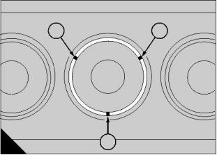
7 Measure and record the liner flange protrusion
above the crankcase top face at four equidistant
points.
Protrusion limits are 0,076 to 0,127 mm (0.003 to
0.005 in) and must also meet the following
requirements (A).
z
Maximum variation of 0,025 mm (0.001 in)
between the highest and lowest points on any one
liner flange.
z
Maximum variation of 0,025 mm (0.001 in)
between protrusions at adjacent points of
neighbouring liners.
8 Use ‘Engineers blue’ to check the contact between
the liner flanges and their seating faces. To ensure a
satisfactory seal, the contact area must cover 100%
of the circumference and at least 50% of the width
and any position. If the area of contact does not
conform to these requirements, the flange of the
cylinder liner must be lapped to the shoulder in the
crankcase by the use of a lapping compound. A
lapping tool, 21825 902, is available for this operation.
Continued
0.114
0.089
0.076
0.089
0.114
0.127
0.127
0.102
0.102
0.076 0.076 0.076
0.076
0.076
0.102
0.102
0.127
0.127
0.114
0.089
0.076
0.127
0.076
0.089
0.127
Acceptable
0.127
0.102
0.076
0.127
0.114
0.127
0.076
0.076
0.127 0.076
0.076
0.076
0.076
0.127
0.127
0.127
0.076
0.102
0.102
0.114
0.076
0.127
0.102
Unacceptable
A
156
Perkins Engines Company Limited
83
This document has been printed from SPI². Not for Resale
![]()
![]()
16
When a new liner is fitted and the protrusion check is
satisfactory, etch its position number on the top face
(A2) of the liner adjacent to the large coolant port. Do
NOT mark the flange face (A1).
1
2
9 When the protrusion check for the cylinder liners is
satisfactory, remove the liners and ensure that the
seats are clean and have been degreased.
10 Fit the cylinder liners, operation 16-4.
11 Rotate the build stand until the engine is almost
horizontal. Assemble the pistons and connecting rods
as detailed in section 13 and clean the bores of the
cylinder liners. Before each piston assembly is fitted,
turn the crankshaft until the appropriate journal is at
its lowest position. Clean the journal and lubricate
with clean engine oil.
A
292
12 Fit the upper half of the big end bearing to the
connecting rod, ensuring that the location tang is
correctly fitted. Lubricate the bearing with clean
engine oil. Enter the piston/connecting rod assembly
through the compression sleeve tool, 21825 784, into
the bore with the ‘FRONT’ marking on the piston
crown to the front of the engine. Guide the rod
carefully onto the crank pin.
13 Fit the lower half of the bearing into the big end
cap ensuring correct location, and lubricate with clean
engine oil. Fit the bearing cap with the correlation
marks aligned, ensure that the big end bolts are
correctly seated and tighten the lightly oiled nuts to a
torque of 217 Nm (160 lbf ft). Repeat the procedure
for the remaining five assemblies.
14 Fit the six piston cooling jets, complete with new
‘O’ ring seals, secure each with a bolt and spring
washer.
15 Rotate the build stand until the engine is upright.
Turn the crankshaft until the piston is at TDC (top
dead centre) and measure the clearance of the piston
crown below the crankcase top face. A dial gauge,
21825 782, is obtainable for this purpose. Permissible
clearance is 0,28 to 0,38 mm (0.011 to 0.015 in). If
necessary, it is permissible to machine up to a
maximum of 0,127 mm (0.005 in) from the piston
crown. Perform the check on all pistons. Restore the
‘FRONT’ and other markings if they are removed
during machining.
16 Fit the two rocker gear oil feed studs and the
blanking plug, complete with new sealing washer, to
the crankcase top face. Ensure that the feed stud
oilways are clear before fitting.
Continued
84
Perkins Engines Company Limited
This document has been printed from SPI². Not for Resale
![]()
![]()
16
17 Fit a new ‘O’ ring seal to the oil transfer tube and
position the tube in the crankcase front end face. Fit
the two dowels to the front face and position a new
gasket over the dowels. Fit the backplate and retain
with three bolts with plain and spring washers.
1
18 Fit the fuel injection pump adaptor using new ‘O’
rings on the spigot and between the adaptor and
backplate. Fit the rear support bracket to the
crankcase and loosely attach the support block.
19 Lightly smear the camshaft journals and bearing
surfaces with clean engine oil and insert the camshaft
into the crankcase.
3
2
20 For engines with the bolt-on type of camshaft gear
A
295
proceed as follows:
Fit the thrust plate and tighten the capscrews to a
torque of 54 Nm (40 lbf ft). Fit the camshaft drive
gear and secure with a dowel and five setbolts
tightened to a torque of 61 Nm (45 lbf ft). Bend up
the tabs of the locking plate.
For engines with the integral type of camshaft gear
proceed as follows:
Rotate the camshaft gear until the capscrews
which retain the thrust plate can be fitted through
the access holes in the camshaft gear. Tighten the
capscrews evenly to a torque of 54 Nm (40 lbf ft).
21 Fit the fuel injection pump drive gear and secure
with retaining plate and bolts.
22 For new 2000 series engines: Fit the dowel for the
idler gear axle, fit the axle, fit the gear and collar and
retain with the capscrew. For earlier engines: Fit the
idler gear axle locating dowels and retain the axle with
three setscrews. Fit the idler gear. For all engines,
align the timing marks as shown (A).
Note: On early engines, if a new idler gear, a new
idler gear axle or a new crankcase is used, the
position of the idler gear axle must be set correctly to
obtain the correct backlash for the gears. Refer to
operation 15-7.
23 Ensure that the crankcase and cylinder head
flame faces are clean and dry. Fit the coolant bobbins,
complete with new ‘O’ ring seals, into the top face of
the crankcase. Fit the dowels and the new cylinder
head gaskets, noting that the gaskets are marked
‘TOP’, and lower the cylinder heads into position. A
lifting bar, 21825 816, is obtainable for this purpose.
Continued
Perkins Engines Company Limited
85
This document has been printed from SPI². Not for Resale
![]()
![]()
![]()
16
24 Position the lifting eyes. A light application of oil
must be applied under the head of each cylinder head
bolt and also to the threaded area. Do NOT use an
excess amount of oil. Where relevant, fit a washer to
each bolt.
Note: Recent engines use a different type of bolt
which MUST be fitted without a washer.
25 Screw the bolts in by hand to ensure the correct
location. Always place the bolts in position, do NOT
drop them. Lightly oil the threads on the oilway stud
and fit the nut and washer. Later engines have a
special bolt (A22) fitted in place of the stud and nut.
Caution: The special bolt (at position A22) is drilled
and can be identified by the word ‘OIL’ stamped on its
head or, for later engines, a recess in its head. The
old and new types of drilled bolt are interchangeable.
A
56
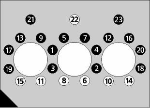
26 Align the heads by temporarily fitting the inlet
manifold without the gasket and, using the sequence
shown (A), tighten the bolts (and nut where relevant)
of each cylinder head as follows:
a Tighten all bolts in the sequence shown (A) to a
torque of 136 Nm (100 lbf ft).
b Tighten all bolts in the sequence shown (A) to a
torque of 204 Nm (150 lbf ft).
c Tighten ONLY the bolts in the black circles, in
the sequence shown (A), by an additional angle
of 40 degrees. A torque angle gauge, 21825
924, is available for this purpose.
Remove the inlet manifold.
Caution: Except for new 2000 series engines, the
bolts and nuts of a newly fitted cylinder head must
be re-tightened to their final torque figures, and the
tappet clearances checked, after the first 500 to
1000 km.
27 Lightly oil the cam followers and fit them to their
relevant positions in the crankcase. Fit the rocker oil
feed pipe and secure with three bolts and shouldered
washers. Fit the gasket, baffle plate, gasket and the
tappet cover and secure the engine breather pipe to
the tappet cover. If the engine is fitted with an oil
distribution block it should now be refitted complete
with plugs and adaptors as appropriate.
Continued
86
Perkins Engines Company Limited
This document has been printed from SPI². Not for Resale
![]()
![]()
16
28 Fit the push rods and assemble the rocker gear.
Refer to section 11 for torque settings. To facilitate
barring over the crankshaft, screw two bolts into its
rear face. Turn the crankshaft anticlockwise, viewed
from the flywheel end, and adjust the tappet
clearances in the sequence which follows. ‘Valves
rocking’ means ‘inlet valve just opening, exhaust
valve just closing’.
Valves rocking on
cylinder number
Adjust tappets on
cylinder number
No.6
No.3
No.5
No.1
No.4
No.2
No.1
No.4
No.2
No.6
No.3
No.5
Adjust the valve tappet clearances, as shown (A), to
these dimensions:
Inlet valves:
0,25 mm (0.010 in).
0,50 mm (0.020 in).
Exhaust valves:
29 Re-check each clearance after tightening the lock
nut of the adjusting screw to 40 Nm (30 lbf ft). Do not
fit the rocker covers permanently until the injection
pump timing procedure has been done. Pour oil over
the rocker and valve assemblies and fit the rocker
covers.
A
151
30 Fit the air inlet manifold/charge cooler assembly,
use new gaskets at the joint face. Fit the coolant pipe
between the charge cooler and the rear end of the
crankcase.
31 Fit the rear oil seal housing and oil seal to the
crankcase rear face.
Note: A rear oil seal housing is not fitted to new 2000
series engines.
Rotate the build stand until the sump mounting face is
uppermost.
32 Fit the oil pump dowels and, where necessary, the
original shims, and fit the oil pump complete with drive
gear, to the bearing cap.
Check the drive gear backlash at four equidistant
points on the gear. With the engine upright in the
normal running position, the backlash should be 0,10
to 0,25 mm (0.004 to 0.010 in). Adjust if necessary by
varying the shim thickness between the pump and the
bearing cap. Shims are supplied in thicknesses of 0,2
and 0,3 mm (0.008 and 0.012 in).
Continued
Perkins Engines Company Limited
87
This document has been printed from SPI². Not for Resale
![]()
![]()

16
33 Fit the suction intake assembly, the oil transfer
pipes and connections to the oil pump and crankcase.
34 Fit the wheelcase complete with a new gasket at
the joint face. Before tightening the securing bolts use
a straight edge to align the base with the sump
mounting face, the base should be within 0,08 mm
(0.003 in) of the sump mounting face.
35 Fit the sump guide studs, 21825 812, apply two
lines of Hylogrip sealant along the joints where the
wheelcase meets the backplate and position the new
gasket. Carefully fit the sump, remove the guide studs
and fit the bolts, complete with plain and spring
washers.
1
Caution: When tightening bolts on rear pannier
sumps the four bolts immediately to the front of the
pannier (two each side, near the centre of the sump),
must be tightened last to a torque of 28 Nm (21 lbf ft).
36 With the crankcase in the upright position, fit the
flywheel housing as follows:
For new 2000 series engines, the crankshaft rear oil
seal is fitted directly in the flywheel housing and the
joint between the flywheel housing and the crankcase
must be sealed by the use of a special sealant,
‘Loctite gasket eliminator 518’. Ensure that the faces
of the flywheel housing and crankcase are clean and
dry. Apply a continuous bead of ‘Loctite gasket
eliminator 518’ to the cylinder block as shown (A1).
A
300
For earlier engines, which have a separate housing
for the crankshaft rear oil seal, the flywheel housing is
fitted directly onto the crankcase. No gasket is
required and sealant must NOT be applied.
Lift the housing onto the locating dowels and fit the
retaining bolts and washers. Tighten the bolts evenly
to a torque of 61 Nm (45 lbf ft).
37 Fit the flywheel guide studs, 21825 802, to the
crankshaft, position the flywheel using lifting bracket,
21825 817, ensure that it is correctly located over the
dowel and fit the retaining bolts. Remove the guide
studs, fit the remaining bolts and tighten all bolts to a
torque of 122 Nm (90 lbf ft).
38 Fit and secure the starter motor assembly.
39 Fit the rear cone, the crankshaft hub, the front
cone and the crankshaft nut, ensure that the oil seal
lips are properly positioned on the hub. If an adequate
torque wrench and reduction unit is available, tighten
the crankshaft nut to a torque of 949 Nm (700 lbf ft). If
not, tighten the nut hand-tight then a further two flats
using spanner 21825 807. To ensure alignment of the
nut locking plate the nut may be tightened further but
must NOT be slackened.
Continued
88
Perkins Engines Company Limited
This document has been printed from SPI². Not for Resale
![]()
![]()
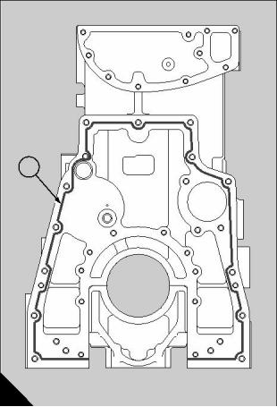
16
40 Fit the fuel injection pump, operation 20-10.
52 Fit the belt tensioner assembly, then the alternator
drive belt and the three main drive belts. Set the belt
tensions as given in section 4 of the User’s
Handbook, TSD3215.
41 Fit the fuel injectors, operation 20-1. Fit both
rocker covers complete with new gaskets.
42 Blow through high pressure fuel pipes with dry
compressed air before proceeding: Loosely fit the
injector feed pipes. Note that the high pressure pipes
of recent engines are joined and must be fitted as a
set. Ensure that each pipe is aligned correctly, press
the rubber shroud inserts over each pipe, then
position the shrouds over the inserts with steel
backplates where necessary. Do NOT bend the
pipes. Tighten the pipe unions taking care not to strain
or twist the pipes. Finally secure the shrouds with
bolts and spring washers.
43 Assemble the coolant rail to the thermostat
housing, using new ‘O’ ring seals on all connections.
Fit the thermostat-to-wheelcase coolant pipe then fit
the coolant rail assembly, complete with thermostat,
and secure to the cylinder heads.
53 Apply a light coat of anti-seize compound to the
mounting stud threads and assemble the
turbocharger unit to the exhaust manifold/mounting
duct. Fit the turbocharger diffuser and the exhaust
outlet pipe, realign the marks which were made during
dismantling to ensure correct orientation. Prime the
1
turbocharger bearings by pouring 0,2 ltr ( / pint) of
3
clean engine lubricating oil into the aperture at the top
of the bearing housing. Check the turbocharger oil
feed and drain pipes for damage and restrictions and
assemble to the engine complete with new gaskets
where necessary. Fit the duct between the
turbocharger and the air inlet manifold, use a new
seal at the ‘V’ band camp end. Tighten ‘V’ band
clamps to a torque of 8 Nm (6 lbf ft).
54 Remove the engine from the build stand,
44 Fit the fuel filter bracket and fit the low pressure
fuel pipes, check all pi, pes for cleanliness before
fitting. Strict cleanliness must be observed when
assembling pipes and fittings to the engine. Fit a new
fuel filter canister as described in the User’s
Handbook TSD3215.
operation 16-1.
45 Position a new coolant pump gasket and fit the
coolant pump, connect the relevant hoses and
connections and fit the alternator adjusting strap
beneath the relevant cover bolt. Fit the coolant pump
drive pulley and tighten the securing bolts to a torque
of 24 Nm (18 lbf ft).
46 Fit the crankshaft damper, locking plate and main
pulley and secure with bolts and spring washers.
Tighten the bolts to a torque of 41 Nm (30 lbf ft).
47 Assemble the exhaust manifold and, using new
gaskets, bolt the assembly to the cylinder heads. Use
the two tie plates between diagonally opposite bolts at
the number 2 and 5 cylinder positions and apply
Rocol J-166 to the bolt threads before fitting.
48 Mount the compressor, complete with drive gear,
on the rear of the backplate, use a new gasket at the
joint face and secure with three bolts, nuts and spring
washers. For engines without compressors the
banking plate should be fitted.
49 Connect the coolant pipework between the
crankcase and the compressor and the compressor
and the base of the thermostat housing. Fit the
compressor air filter and pipework.
50 Fit the oil filler assembly, complete with a new
gasket. Fit the dipstick assembly.
51 Secure the alternator mounting bracket and
alternator to the coolant pump outlet connection, fit
plain and spring washers to each bolt. Attach the
alternator to its adjusting strap but do not tighten. On
new engines the alternator mounting is an integral
part of the coolant pump cover.
Perkins Engines Company Limited
89
This document has been printed from SPI². Not for Resale
![]()
![]()
16
To inspect
16-3
Special tools:
Remover tool for cup plugs, 21825 855
Slide hammer, 21825 849
Replacer kit for cup plugs, 21825 865
Drive handle, 21825 861
Cutting tool, 21825 791
Cutter, 21825 792
Crankcase
A
303
Remove all blanking plugs and clean the crankcase
thoroughly giving special attention to oilways. Refit
the coolant plugs to the cylinder block, apply ‘Loctite
225’ to the threads and use new sealing washers
where necessary. Remove any suspect core plugs
using the core plug remover, 21825 855, and slide
hammer, 21825 849. To fit new core plugs use the
replacer kit, 21825 865, and drive handle, 21825 861.
Test the crankcase for cracks as follows: make,
locally, enough seals to close all of the coolant
apertures and fit them to the crankcase. Immerse the
crankcase in water which has been maintained at
60°C (140°F) for 20 minutes. Apply air pressure at
207 kN/m² (30 lbf/in²) and examine for leaks. If there
is a fault in the casting, contact the service
department at Perkins Engines Company Limited
Shrewsbury.
Top face
Eroded bobbin recesses and fretting of the crankcase
top face may be rectified. Details of the relevant
service reclamation schemes may be obtained from
the Service Department at Perkins Engines Company
Limited, Shrewsbury. A range of service undersize
pistons is available for use when the top face of the
crankcase has been machined.
Liner recesses
Check each liner flange seat for fretting or cracks.
A cutting tool (A), 21825 791 and cutter 21825 792,
may be used to restore unsatisfactory seats or to
restore seat depths after the top face of the crankcase
has been machined.
Inspect the lower recesses for erosion and damage
around the sealing areas. Instructions for any
necessary repairs may be obtained from the Service
Department at Perkins Engines Company Limited,
Shrewsbury.
90
Perkins Engines Company Limited
This document has been printed from SPI². Not for Resale
![]()
![]()
![]()
![]()
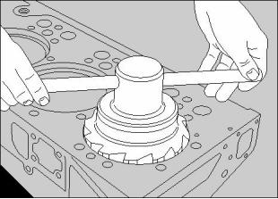
16
Cylinder liners
1
2
To remove and to fit
16-4
Special tools:
Remover/replacer tool, 21825 790
Cylinder liner clamp, 21825 844
To remove
1 Drain cooling and engine lubrication systems.
2 Remove the cylinder head/s, operation 12-4.
A
141
3 Remove the sump, operation 19-3, and remove the
pistons, operation 13-1.
4 Turn the engine to a vertical position with the flame
face uppermost.
5 Extract the cylinder liners using the special tool,
21825 790. Remove and discard the sealing rings.
6 Inspect the cylinder liners, operation 16-5.
Caution: Ensure that the cylinder liners are not
damaged while they are out of the crankcase.
To fit
Before each cylinder liner is fitted, it is recommended
that ‘Loctite Ultra Copper Sealant’ (Loctite 5920) is
applied to the crankcase (A1) around the seats for the
cylinder liner flanges. ‘Linalube’ must be applied to
the sealing ring area at the lower end of the cylinder
bore.
B
298
Ensure that the cylinder liner seats are clean and
have been degreased.
1 Apply a thin smear of ‘Linalube’ to the sealing ring
area at the base of each cylinder bore. Ensure a
100% covering of that area. Repeat the procedure for
each cylinder.
1
2 Apply ‘Loctite 5920’ as a bead of 2-3 mm ( / in)
8
diameter (A2). Ensure that the sealant is applied
evenly around the whole circumference. Do NOT
apply too much sealant. Repeat the procedure for
each cylinder.
Warning! ‘Loctite Ultra Copper Sealant’ starts to
harden after 30 minutes.
3 Apply a light smear of ‘Linalube’ to the sealing rings
and fit them to the liner as shown (B). Ensure that the
white marks on the sealing rings are on the outside
and face towards the liner flange.
Caution: An excessive quantity of ‘Linalube’ may
cause hydraulic locking during fitting of the liner.
Continued
Perkins Engines Company Limited
91
This document has been printed from SPI². Not for Resale
![]()
![]()
![]()
![]()
![]()
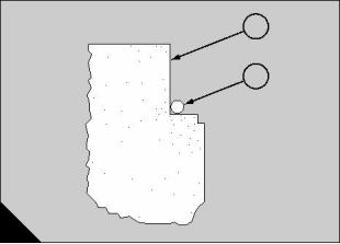
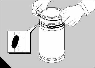
16
4 Liners may be pressed in by hand. If difficulties are
encountered it is advisable to withdraw the liner and
check that the rings are correctly fitted and that an
excessive amount of ‘Linalube’ has not been applied.
As each cylinder liner is fitted, fit a cylinder liner
clamp, 21825 844, to retain it securely.
Do NOT use mineral oil on the crankcase and sealing
rings if ‘Linalube’ is not available. Tight liners may be
pressed in using the remover/replacer tool, 21825
790 (A).
5 After the cylinder liners have been fitted, check the
bores (B) for ovality and taper. The maximum
acceptable limit for both taper and ovality is 0,05 mm
(0.002 in). The lower bore dimension should not be
less than 130,14 mm (5.124 in).
A
296
6 Remove the clamps and fit the pistons, operation
13-1.
7 Fit the cylinder heads, operation 12-4.
8 Fit and the sump, operation 19-3. Fill the coolant
and lubrication systems to the correct levels.
To clean and to inspect
16-5
Ensure that the seals have been removed. Soak the
liners in a carbon solvent, such as Ardrox 667 or
Maxan 776. See Warnings and instructions on how to
use these solvents on page 16.
Check for cracks in each cylinder liner by use of the
electro-magnetic method if possible. Inspect the top
flange for fretting and the coolant areas for erosion
and pitting. Special attention should be given to the
area of the sealing ring grooves. Unserviceable
cylinder liners must be renewed.
Silicon carbide liners are fitted and they MUST NOT
BE RE-HONED.
Cylinder liners with a thicker flange are available to
enable correct liner protrusion to be established after
restoration work. These liners are identified by a
groove machined around the top flange. Cylinder
liners with thicker flanges are available in two sizes:
+0,05 mm (+0.002 in) and +0,127 mm (+0.005 in).
B
297
When a new liner is fitted, etch its cylinder position
number on the liner top face on satisfactory
completion of the protrusion check given on page 83.
92
Perkins Engines Company Limited
This document has been printed from SPI². Not for Resale
![]()
![]()
![]()
![]()
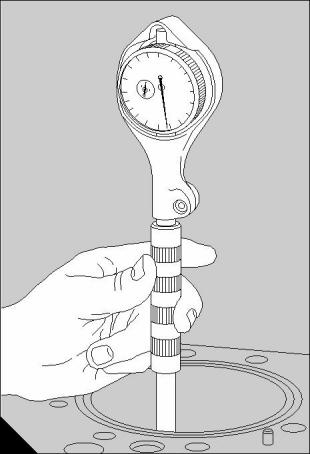
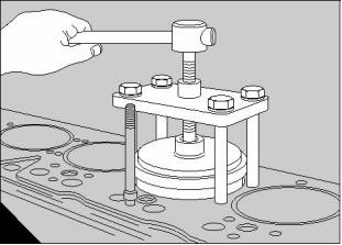
16
Cam followers
To fit
1 Ensure that the joint faces on the cover plate and
crankcase are clean.
To remove and to fit
16-6
2 Lightly smear the cam followers with clean engine
oil and fit them to the correct positions in the
crankcase.
To remove
1 If a compressor is fitted to the engine, drain the
coolant system to below the level of the coolant inlet
pipe of the compressor.
2 Remove the rocker covers and the rocker
assemblies, operation 12-1 and operation 12-2.
Withdraw the push rods and store them in the correct
sequence to ensure that they can be refitted to their
original positions.
3 Fit the baffle and cover plate, complete with new
joints.
4 Fit the breather pipe to the cover and tighten the
clip.
5 Fit the oil feed pipe, the coolant pipes and the air
supply pipe to the compressor.
6 Fit the push rods to the relevant cam followers. Fit
the rocker assembly, operation 12-2, and adjust the
tappets, operation 12-3.
3 Where fitted, disconnect and remove the oil feed
and coolant pipes from the compressor, and remove
the compressor air supply pipe.
7 Fit the rocker covers, operation 12-1.
8 If the coolant system was drained, fill to the correct
4 Slacken the hose clip and remove the breather pipe
level with the approved coolant mixture.
from the cam follower cover.
5 Remove the cam follower cover and withdraw the
baffle. Discard the joints.
6 Lift out the cam followers. Keep the cam followers
in the correct sequence to ensure that they can be
refitted to their original positions.
Inspect the cam followers for wear and scuffing, and
check each one in its respective bore. If the cam
follower is otherwise serviceable, slight damage may
be removed by the use of a smooth oilstone.
Perkins Engines Company Limited
93
This document has been printed from SPI². Not for Resale
![]()
![]()
![]()
![]()
16
Camshaft
1
To remove and to fit - bolt-on type
16-7
To remove
1 Remove the cam followers, operation 16-6.
2 Remove the alternator, operation 23-2.
3 Remove the coolant pump, operation 21-5.
4 Remove the crankshaft pulley assembly, operation
14-1 or operation 14-2, and the wheelcase, operation
15-1.
3
2
A
295
5 Turn the engine until No.1 piston is at TDC with the
relevant mark on the flywheel aligned with the timing
pointer in the flywheel housing. The timing marks on
the camshaft and crankshaft gears should now be
facing the idler gear axle as shown (A), and the mark
on the front end of the crankshaft at the 12 o’clock
position.
6 Remove the five bolts from the drive gear and
withdraw the gear.
7 Unscrew and remove the thrust plate.
8 Carefully withdraw the camshaft.
To fit
1 Lightly smear the journals and bearing surfaces
B
305
with clean engine oil and carefully insert the camshaft.
7 Fit the wheelcase, operation 15-1.
2 Ensure that the thrust plate bolts and their
respective holes in the crankcase are clean and free
from grease. Fit the thrust plate. Apply ‘Loctite 242’ to
the threads of the bolts, fit the bolts and tighten each
bolt to a torque of 54 Nm (40 lbf ft).
3 Fit and secure the camshaft gear (A3) to the
camshaft with the timing mark aligned with the
corresponding marks on the idler gear (A1). Fit the
locking plate, if one was previously fitted, fit the
retaining bolts, tighten them to a torque of 61 Nm (45
lbf ft) and bend up the tabs on the locking plate.
Check the end float as shown (B). Limits for end float
are 0,152 to 0,405 mm (0.006 to 0.016 in).
8 Fit the crankshaft pulley assembly, operation 14-1
or operation 14-2.
9 Fit the coolant pump, operation 21-5.
10 Fit the alternator, operation 23-2.
11 Fit the cam followers, operation 16-6.
4 If the end float exceeds the limits it must be
corrected by fitting a new thrust plate or drive gear.
5 When the end float is correct, check that the gear
retaining screws are tightened to the correct torque
figure, 61 Nm (45 lbf ft).
6 Ensure that the timing marks on the idler gear (A1),
crankshaft gear (A2) and camshaft gear (A3) are
correctly aligned. Check the backlash between the
idler gear and the camshaft gear, and also between
the idler gear and the crankshaft gear. Refer to Fits
and clearances on page 77.
94
Perkins Engines Company Limited
This document has been printed from SPI². Not for Resale
![]()
![]()
![]()
![]()
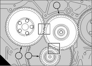
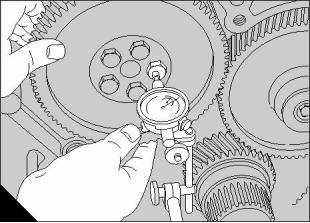
16
Camshaft
To remove and to fit - integral type
16-8
To remove
1 Remove the cam followers, operation 16-6.
2 Remove the alternator, operation 23-2.
3 Remove the coolant pump, operation 21-5.
4 Remove the crankshaft pulley assembly, operation
14-1 or operation 14-2, and the wheelcase, operation
15-1.
A
306
5 Remove the idler gear.
6 Rotate the camshaft gear until the capscrews which
retain the thrust plate can be seen through the access
holes in the gear.
1
7 Remove the thrust plate capscrews.
8 Carefully withdraw the camshaft.
To fit
1 Turn the engine until the number 1 piston is at TDC
with the mark on the end of the crankshaft at the top
position.
2 Lightly smear the camshaft journals and bearing
surfaces with clean engine oil and carefully insert the
camshaft into the crankcase.
3
2
B
304
3 Rotate the camshaft gear until the capscrews which
retain the thrust plate can be fitted through the access
holes in the gear. Ensure that the capscrews and their
respective holes in the crankcase are clean and free
from grease. Apply ‘Loctite 242’ to the threads of the
capscrews, fit the capscrews and tighten each to a
torque of 54 Nm (40 lbf ft).
4 Check the camshaft end float as shown (A).
Limits for end float are 0,152 to 0,405 mm (0.006 to
0.016 in). If the end float exceeds the limits it must
be corrected by fitting a new thrust plate or drive
gear.
5 Fit the idler gear.
6 Ensure that the timing marks on the idler gear (BI),
the crankshaft gear (B2) and the camshaft gear (B3)
are correctly aligned.
7 Check the backlash between the idler gear and the
camshaft gear, and also between the idler gear and
the crankshaft gear. Refer to Fits and clearances on
page 77.
8 Fit the wheelcase, operation 15-1.
9 Fit the crankshaft pulley assembly, operation 14-1
or operation 14-2.
10 Fit the coolant pump, operation 21-5.
11 Fit the alternator, operation 23-2.
12 Fit the cam followers, operation 16-6.
Perkins Engines Company Limited
95
This document has been printed from SPI². Not for Resale
![]()
![]()
![]()
![]()
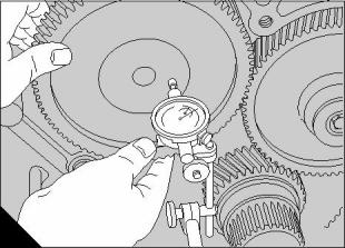
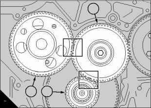
16
To inspect
16-9
1 After the camshaft has been removed from the
crankcase, clean thoroughly and check for cracks.
The electro-magnetic method is recommended. If this
method is not available, use the dye penetrant
process.
2 Check the cams and journals for wear or damage.
Small marks can be removed by the use of a smooth
oilstone. Ensure that the shape of each cam is not
affected.
3 Check the thrust plates for wear or damage and
renew them if necessary.
4 Where necessary, check the camshaft bush in the
crankcase for wear or damage and renew if
necessary. New camshaft bushes are a tight fit in the
crankcase.
5 With the camshaft fitted in the crankcase, check the
end float as given in operation 16-7 or operation 16-8.
If the end float exceeds the limits it must be corrected
by fitting a new thrust plate or drive gear.
6 Check the backlash between the idler gear and the
camshaft gear, and also between the idler gear and
the crankshaft gear. Backlash dimensions are given
on page 77.
96
Perkins Engines Company Limited
This document has been printed from SPI². Not for Resale
![]()
![]()
![]()
16
Fits and clearances
1
2
3
7
6
5
4
A
294
Cylinder liners in the cylinder block
Liner flange bore in cylinder block (A2) . . . . . . . . . . . . . . . . . . . . . 155,067 to 155,143 mm (6.105 to 6.108 in)
Outside diameter of cylinder liner flange . . . . . . . . . . . . . . . . . . . . 154,788 to 154,838 mm (6.094 to 6.096 in)
Clearance (new) . . . . . . . . . . . . . . . . . . . . . . . . . . . . . . . . . . . . . . . . . . 0,229 to 0,355 mm (0.009 to 0.014 in)
Depth of counterbore in the cylinder block (nominal) (A1) . . . . . . 12,588 to 12,591 mm (0.4956 to 0.4957 in)
Depth of the flange of the cylinder liner (nominal). . . . . . . . . . . . . . . 12,675 to 12,700 mm (0.500 to 0.499 in)
Protrusion of the cylinder liner above the flame face of the crankcase . 0,076 to 0,127 mm (0.003 to 0.005 in)
Caution: Cylinder liners must be selected carefully to obtain the correct protrusion dimensions.
Cylinder liners when not fitted to the cylinder block
Bore of cylinder liner (A3) . . . . . . . . . . . . . . . . . . . . . . . . . . . . . . 130,175 to 130,2005 mm (5.125 to 5.126 in)
Permissible worn dimension . . . . . . . . . . . . . . . . . . . . . . . . . . . . . . . . . . . . . . . . . . . . . 130,480 mm (5.137 in)
Perkins Engines Company Limited
97
This document has been printed from SPI². Not for Resale
![]()
![]()
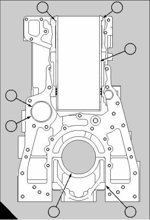
16
1
2
3
7
6
5
4
A
294
End float of camshaft
Clearance (new). . . . . . . . . . . . . . . . . . . . . . . . . . . . . . . . . . . . . . . . . . . . 0,152 to 0,40 mm (0.006 to 0.016 in)
Permissible worn clearance. . . . . . . . . . . . . . . . . . . . . . . . . . . . . . . . . . . . . . . . . . . . . . . . . 0,51 mm (0.020 in)
Camshaft bearings
Bore in cylinder block (A6). . . . . . . . . . . . . . . . . . . . . . . . . . . . . . . 66,027 to 66,053 mm (2.5995 to 2.6005 in)
Diameter of camshaft journals . . . . . . . . . . . . . . . . . . . . . . . . . . . . 65,875 to 65,900 mm (2.5935 to 2.5945 in)
Clearance. . . . . . . . . . . . . . . . . . . . . . . . . . . . . . . . . . . . . . . . . . . . . . . . 0,127 to 0,177 mm (0.005 to 0.007 in)
Permissible worn clearance. . . . . . . . . . . . . . . . . . . . . . . . . . . . . . . . . . . . . . . . . . . . . . . . 0,254 mm (0.010 in)
Shell-type camshaft bearing
Note: A bearing is only fitted to the front position on non-generator set industrial engines.
Bore in cylinder block (A6). . . . . . . . . . . . . . . . . . . . . . . . . . . . . . . 70,091 to 70,117 mm (2.7595 to 2.7605 in)
Bore of shell-type bearing when installed in crankcase (A7) . . . . 65,9765 to 66,040 mm (2.5975 to 2.6000 in)
Main bearing housing in crankcase
Bore of bearing housing (A5). . . . . . . . . . . . . . . . . . . . . . . . . . . . . 104,140 to 104,165 mm (4.100 to 4.101 in)
Bearing caps in crankcase
Width in crankcase for bearing cap (A4) . . . . . . . . . . . . . . . . . . . . 168,275 to 168,300 mm (6.625 to 6.626 in)
Width of bearing cap . . . . . . . . . . . . . . . . . . . . . . . . . . . . . . . . . 168,283 to 168,295 mm (6.6253 to 6.6258 in)
Fit (new). . . . . . . . . . . . . . . . . . . . . . . . 0,018 mm (0.0007 in) clearance to 0,020 mm (0.0008 in) interference
98
Perkins Engines Company Limited
This document has been printed from SPI². Not for Resale
![]()
![]()

17
Engine timing
17
Valve timing
1
To check
17-1
Caution: This operation requires a high degree of
accuracy to avoid a false reading.
1 Remove the timing pointer cover from the flywheel
housing.
2 Remove the rocker covers and joints.
3 Turn the engine forward (clockwise viewed from the
front) until the valves of No. 6 cylinder are ‘rocking’
(i.e., inlet valve just opening and exhaust valve just
closing).
3
2
A
295
4 Adjust the clearance of the No. 1 cylinder inlet valve
to 0,89 mm (0.035 in).
5 Continue turning the engine forward until a 0,13 mm
(0.005 in) feeler gauge is just nipped between the
No. 1 inlet valve rocker arm and its valve stem. The
inlet valve opening mark ‘V1’ on the flywheel should
now be aligned with the flywheel housing timing
pointer.
6 If satisfactory, return the engine to the No. 6
cylinder valves ‘rocking’ position. If not, check the
timing gear marks (A).
On completion, proceed as follows:
1 Reset No. 1 cylinder inlet valve clearance to
0,25 mm (0.010 in) and fit the timing pointer cover.
2 Remove the joints from the rocker covers and
clean the corresponding faces of the covers and
cylinder head. Fit new joints to the rocker covers,
ensuring that they are correctly located within the
slots in each cover, and fit the covers. Secure each
cover with the three cap nuts and check that the
joints have not moved. Tighten the cap nuts evenly
to a torque of 11 Nm (8 lbf ft). Do NOT over tighten.
Perkins Engines Company Limited
99
This document has been printed from SPI². Not for Resale
![]()
![]()
![]()
![]()

17
Fuel injection pump timing
To check and to adjust
17-2
1 The injection timing position is stamped on the
engine data plate.
1
2 Secure the stop lever in the NO FUEL position and
remove the front rocker cover.
3 Turn the engine in the normal direction of rotation
(anti-clockwise viewed on flywheel) until No. 1 inlet
valve closes. Remove the timing pointer cover (A1)
from the side of the flywheel housing.
Note: The position of the timing pointer on the
flywheel housing depends on the type and age of the
engine. For new engines the timing pointer is at the 10
o’clock position when viewed from the rear of the
engine.
A
B
C
D
307
308
309
310
4 Continue turning the engine until the figure on the
flywheel, corresponding to that stamped on the
engine data plate, aligns with the timing pointer in the
flywheel housing aperture.
5 Remove the cap nut from the fuel injection pump
and withdraw the timing pointer location device (B1).
Ensure that the timing pointer (C1) is now visible
through the aperture.
1
6 Invert the location device and refit it to its original
position with the location slot horizontal. If the timing
is correct the location device (D1) will enter fully.
Continued
1
1
100
Perkins Engines Company Limited
This document has been printed from SPI². Not for Resale
![]()
![]()
![]()
![]()
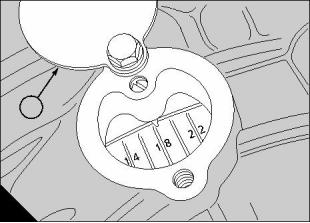
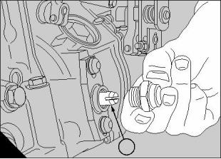
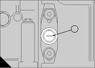
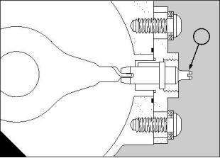
17
7 If the location device does not enter fully the timing
is incorrect and the access cover (A1) must be
removed from the front of the engine.
8 Slacken the four gear retaining bolts (B) and turn
the pump camshaft, with a 30 mm spanner, until the
location device enters fully under light pressure.
9 Tighten the gear retaining bolts to a torque of 45 Nm
(33 lbf ft) and withdraw the location device.
10 Turn the engine backwards a minimum of 60
degrees and repeat paragraphs 4, 5 and 6.
11 If timing is still incorrect repeat paragraphs 4 to 9
inclusive.
12 Proceed as follows when the timing is correct.
13 Fit the front access cover plate.
14 Withdraw the location device (C1), invert it and
refit it as shown (C). The pointer location slot MUST
face outwards. Fit the cap nut.
15 Fit the rocker cover, release the engine stop lever
and fit the timing pointer cover plate to the flywheel
housing.
1
A
B
C
311
1
312
1
313
Perkins Engines Company Limited
101
This document has been printed from SPI². Not for Resale
![]()
![]()
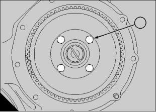
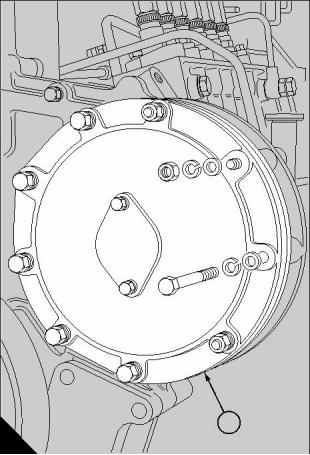
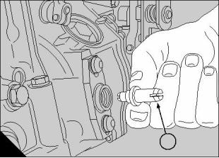
This document has been printed from SPI². Not for Resale
18
Aspiration system
18
General description
The induction system of the engine is supplied with air Aspiration system maintenance
under pressure by means of a turbocharger driven by
the energy of the waste exhaust gases. The part
number of the turbocharger can be found on the
turbocharger data plate. Early engines are fitted with
one of these: OE49342, OE51140 or OE51430. New
2000 series engines are fitted with OE52534 or
OE52535. TTAG engines are fitted with two
turbochargers: OE50642 and OE50674.
The following points should receive particular
attention:
1 Service the air cleaner in accordance with the
Perkins recommendations given in section 4 of the
User’s Handbook, TSD3215, or in the equipment
manufacturer’s manual.
2 At frequent intervals inspect the induction and
exhaust systems for leakage and deterioration of
hose connections. If the systems are disturbed they
must be reassembled carefully to ensure perfect
joints and to prevent cracking of manifolds due to
uneven tightening.
3 During servicing, take special care to prevent dirt
and loose articles from entering the induction and
exhaust systems where they could damage the
compressor or turbine wheels of the turbocharger.
4 The exhaust manifolds are made from a special
alloy to protect the turbocharger turbine wheel from
damage by loosened scale. Manifold components
designed for non-turbocharged engines are not
suitable for use in conjunction with a turbocharger.
5 At frequent intervals check that the turbocharger oil
feed and drain pipes are undamaged. Restriction of
oil flow may result in turbocharger bearing failure.
Check the bore of the drain pipe at oil change
intervals.
6 Use an approved lubricating oil of the correct grade
and specification and maintain the engine lubrication
system in accordance with the User’s Handbook,
TSD3215.
7 Make periodic checks to ensure that the exhaust
system is unrestricted (for example: by choked
silencer or damaged exhaust pipe). Overheating and
loss of performance will occur if the exhaust back-
pressure exceeds 51 mm (2 in) Hg under full load.
Turbochargers OE51430 and OE52535 are each
fitted with a waste-gate.
The exhaust manifolds direct the exhaust gases to the
turbine wheel of the turbocharger rotor, causing the
rotor to spin. The turbocharger compressor impeller,
which forms part of the rotor assembly, draws air in
through the air cleaner and delivers it to the induction
manifold, under pressure, to be distributed to each
cylinder as the inlet valves open. A waste-gate, fitted
to certain turbochargers, monitors the boost delivery
pressure in the turbocharger compressor and, once
this reaches a pre-set figure, opens and allows the
excess pressure to escape.
TWG engines are fitted with an air-to-coolant charge
cooler, interposed between the turbocharger and the
induction manifold. This serves to lower the
temperature of the compressed induction charge
before it passes into the engine. The charge cooler is
supplied by coolant from the engine. The coolant
flows through a matrix of tubes within the charge
cooler before recirculating through the engine coolant
system.
All TA, TAG, and TTAG engines are fitted with an air-
to-air charge cooler, an intercooler. It is mounted at
the front face of the coolant radiator. The
turbocharger compressor directs air through the
intercooler before it passes through large bore
pipework into the induction manifold.
8 If investigation of an engine fault involves checking
the turbocharger, remove the trunking and spin the
rotor assembly by hand. Check for freedom to rotate
and listen for noises indicating binding or rubbing. If
necessary, remove the turbocharger for cleaning and
bearing checks, as described later.
Continued
Perkins Engines Company Limited
103
This document has been printed from SPI². Not for Resale
![]()
![]()
18
9 Certain turbochargers are fitted with a waste-gate.
The operation of the waste-gate must be checked at
the intervals specified in the service schedule given in
the User’s Handbook, TSD3215.
Caution: If a new turbocharger is fitted or if a
turbocharger has been removed and refitted to an
engine, it must be primed with clean engine oil of the
correct specification before the engine is first started.
Refer to operation 18-1.
104
Perkins Engines Company Limited
This document has been printed from SPI². Not for Resale
![]()
![]()
18
Turbocharger
To fit
1 Clean the exhaust manifold and turbocharger
mating faces, position the turbocharger on the
exhaust manifold and secure with nuts and plain
washers.
2 Fit the oil supply and drain pipes. Tighten the two
bolts which retain the oil inlet flange to a torque of
20 Nm (15 lbf ft). Connect the air duct. Where ‘V’
band clamps are used, they should be tightened to
a torque of 8 Nm (6 lbf ft).
Description
The turbocharger is a turbine driven compressor
which utilises the energy of the exhaust gases to
increase the mass of the induction charge.
The unit is secured to the exhaust manifold assembly
and consists of a bearing housing which contains the
rotor assembly and bearings and to which is secured
the turbine and compressor housings.
3 Prime the turbocharger bearing housing as follows:
The rotor bearings are of the fully floating sleeve type.
Lateral location of the rotor and control of end float is
achieved by use of a shaft-mounted thrust ring
assembly and a thrust bearing plate. Filtered oil from
the engine is delivered under pressure to the
turbocharger to provide bearing lubrication.
Clean the area around the blanking plug fitted to the
inlet flange of the oil supply pipe. Remove the plug
and add 0,2 litres of clean engine oil, of the correct
grade, to the bearing housing. Fit and tighten the
blanking plug.
Caution: The turbocharger/s MUST be primed with
Drillings in the bearing housing direct oil to the
bearings and the thrust bearing. The rotor assembly
is sealed at each end by split ring type seals.
clean engine oil before the engine is first started.
If the turbocharger is correctly used and maintained
the life expectancy between overhauls may be
regarded as equal to that of an engine. In the event of
a turbocharger failure the cause must be found and
rectified before a replacement is fitted. It is also
necessary to check that the failure has not caused, or
may eventually cause, any further internal damage to
the engine.
How to check the waste-gate
18-2
1 Apply air pressure up to a maximum of 207 kN/m²
(30 lbf/in²) and feel for movement of the end of the
control rod. This should be about 1,15 mm (0.045 in).
2 If the rod fails to move, disconnect the rod from its
lever and try to move the lever by hand. If the lever is
stiff, that part of the turbocharger must be dismantled
and cleaned.
3 With the rod still disconnected, test the assembly
again with air pressure upto 207 kN/m² (30 lbf/in²). If
the rod fails to move, the diaphragm and rod
assembly must be renewed.
Reconditioned turbochargers are available from
Perkins distributors. Service kits, which include all of
the new parts required for turbocharger overhaul, are
also available from Perkins distributors.
To remove and to fit
18-1
To remove
1 Remove the turbocharger air ducts and the oil feed
and drain pipes. Do NOT damage or bend the pipes.
2 Support the turbocharger, unscrew the four
securing nuts and remove the unit.
Perkins Engines Company Limited
105
This document has been printed from SPI². Not for Resale
![]()
![]()
![]()
![]()
![]()
![]()
18
Turbochargers: OE49342, OE50642,
OE51140, and OE51430
To dismantle and to assemble
18-3
To dismantle
These turbochargers are very similar in both design
and operation.
Refer to the exploded view (A) for itemised parts.
1 Use a scriber to mark the relative positions of the
turbine housing (A23), the bearing housing (A19) and
the compressor housing (A1). This will ensure correct
alignment during reassembly.
Whilst OE49342 is illustrated (A), OE51140 and
OE50642 differ from OE49342 in only minor details.
Turbocharger OE51430 is the same as OE51140
except it is fitted with a waste-gate. The operations
which follow apply to these three types of
turbocharger.
2 Clamp the unit on the turbine inlet flange in a vice
in an upright position.
3 Remove the bolts (A4) and the clamping plates (A2)
Oil pressure with the engine on load must be between
2,0 kgf/cm² (30 lbf/in²) and 4,0 kgf/cm² (60 lbf/in²).
Under idling conditions pressure should not fall below
0,7 kgf/cm² (10 lbf/in²).
and lift off the compressor housing.
Caution: Compressor wheel blades can be easily
damaged with compressor housing removed.
4 Bend back the tabs on the locking plates (A25) and
remove the bolts (A24) and clamping plates (A26)
from the turbine housing (A23). Lift the core assembly
away from the turbine housing.
Caution: Turbine blades can be easily damaged
with the turbine housing removed.
Continued
1
9
12
13
16
17
8
7
6
4
3
2
18
15
14
11
10
26
5
25
24
18
23
22
21
20
17
19
A
302
106
Perkins Engines Company Limited
This document has been printed from SPI². Not for Resale
![]()
![]()
![]()
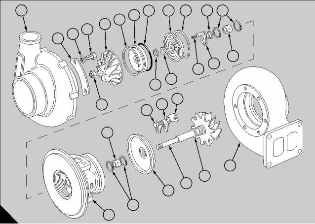
18
5 Use a scriber to mark the relative position of the
compressor impeller (A6) to the turbine shaft (A21).
Hold the turbine wheel in a suitable fixture and
remove the compressor lock nut (A5).
8 When fully assembled, check by hand that the rotor
spins freely.
9 The following specific torques must be applied
during assembly:
Note: Left hand thread. Do NOT bend the shaft.
Bolts (A4)
- 8,5 Nm (75 lbf in)
- 20,3 Nm (180 lbf in)
- 14 Nm (124 lbf in)
- 4,5 Nm (40 lbf in)
6 Slide the compressor impeller (A6) off the shaft.
Bolts (A24)
Lock nut (A5)
Screws (A14)
7 Ease out the retaining ring (A7), using a small
screwdriver, and remove the oil seal plate (A8) from
the bearing housing (A19). Remove the ‘O’ ring seal
(A9) from the bearing housing and push out the oil
slinger (A11) from the oil seal plate.
10 Bend over the tabs of the locking plates on the
turbine and compressor housings.
8 Lift out the oil baffle (A12).
9 Remove the three flat head cap screws (A14) and
withdraw the thrust bearing (A15) and thrust collar
(A16).
10 Remove the shaft assembly (A21) together with
the seal (A22) and remove the heat shield (A20).
11 Remove the outer retaining rings (A17), withdraw
the bearings (A18), and remove the inner retaining
rings (A17).
To assemble
Assembling of the unit is the reversal of the
dismantling procedure after the inspection process
has been completed.
The following points must be observed if a
satisfactory rebuild is to be achieved:
1 Ensure that the parts which have been marked for
alignment purposes are fitted correctly.
2 Bevelled faces of the retaining rings (A17) must be
assembled towards the bearings (A18).
3 Lightly smear all parts with a film of clean engine oil
prior to fitting.
4 Do not force seals (split ring) into bores as they may
fracture and cause binding.
5 Take care not to trap or damage the ‘O’ ring seal
(A9) when assembling the plate (A8) to the bearing
housing (A19).
6 Mount a dial test indicator gauge at the end of the
shaft and check the end float of the shaft between the
extreme positions.
Total travel should be between 0,10 mm to 0,16 mm
(0.004 to 0.006 in).
7 Mount the dial test indicator gauge on the
compressor impeller boss and check the extreme
radial travel by pushing the impeller towards and
away from, in turn, the dial test indicator.
Total travel should be between 0,46 mm and 0,30 mm
(0.018 to 0.012 in).
Note: Readings outside the acceptable travel limits
in paragraphs 6 or 7 will indicate that a complete
overhaul is necessary or that a service replacement is
required.
Perkins Engines Company Limited
107
This document has been printed from SPI². Not for Resale
![]()
![]()
18
To clean and to inspect
18-4
To clean
1 Use a commercially approved non-caustic cleaning
solution to soak parts until all deposits have been
loosened.
2 Clean all aluminium parts with a bristle type brush
or plastic scraper. Vapour blast may be used except
on the shaft and bearing surfaces.
3 Blow compressed air through all drilled
passageways and ensure that the surfaces adjacent
to the turbine and compressor wheels are clean,
smooth and free from deposits.
To inspect
1 Inspect the shaft bearing journals and the walls of
the seal grooves for wear and excessive scratches.
Minor scratches may be tolerated.
2 Check the turbine and compressor wheels for
cracked or damaged blades but do NOT attempt to
straighten blades.
3 Check the thrust bearing surfaces for wear or
damage. Minor scratches are acceptable. Ensure
that the feed grooves in the thrust bearing are clean.
4 Replace the bearings if excessively scratched or
worn.
5 Replace the bearing housing if the bearing or seal
bores are severely scratched or worn.
6 Have the balance of the rotor assembly checked at
an establishment which has the relevant specia, l
equipment and knowledge.
7 Replace the ‘O’ ring seal (A9).
8 Check the turbine housing for signs of rubbing,
flaking and overheating. Slight damage is acceptable
but otherwise the housing should be replaced.
9 Check the compressor housing for damage due to
contact with the rotor. Slight damage is acceptable
but otherwise the housing should be replaced.
108
Perkins Engines Company Limited
This document has been printed from SPI². Not for Resale
![]()
![]()
![]()
18
Caution: Turbine blades can be easily damaged
with the turbine housing removed.
Turbocharger: OE50674
6 Locate the turbine wheel in a 29 mm socket
clamped in a vice or a suitable fixture. Use a scriber
to mark the relative position of the compressor
impeller (A4) to the turbine shaft (A22). Remove the
compressor wheel lock nut (A3).
To dismantle and to assemble
18-5
To dismantle
1 Use a scriber to mark the relative positions of the
turbine housing (A23), the bearing housing (A12), the
compressor housing and the ‘V’ band clamp (A2).
This will ensure correct alignment during reassembly.
Note: Left hand thread. Do NOT bend the shaft.
7 Slide the compressor impeller (A4) from the shaft.
8 Remove the assembly from the socket and
carefully withdraw the turbine shaft and wheel (A22)
from the bearing housing (A12).
2 Clamp the unit on the turbine inlet flange in a vice
in an upright position.
3 Slacken the ‘V’ band clamp and carefully remove
9 Carefully remove the piston ring type seal (A9) from
the compressor housing.
the shaft.
Caution: Compressor wheel blades can be easily
10 Remove the heat shield (A9).
damaged with the compressor housing removed.
11 Secure the bearing housing, with the diffuser (A5)
4 Bend back the tabs on the clamping plates (A15).
Remove and discard the bolts (A16) and clamping
plates
5 Check that the bearing housing and turbine
assembly rotates freely in the turbine housing. If not,
tap the turbine housing (A23) lightly with a copper
hammer. Do NOT hit the turbine wheel to aid removal.
Remove the assembly from the turbine housing
(A23).
uppermost, in a vice fitted with soft jaws.
12 Remove the four diffuser screws and washers. If
the screws are tight, use a penetrating oil to help
loosen them. Discard the screws. Carefully remove
the diffuser.
13 Remove the oil slinger (A7) from the diffuser.
Remove and discard the piston ring type seal (A6)
from the oil slinger.
Continued
1
2
4
3
7
6
5
9
8
12
10
13
16
15
17
18
11
14
21
20
19
22
23
A
333
Perkins Engines Company Limited
109
This document has been printed from SPI². Not for Resale
![]()
![]()
![]()
![]()
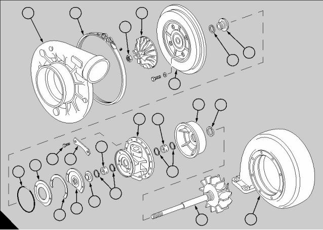
18
14 Remove and discard the oil baffle (A17).
15 Remove the shim (A19).
16 Remove the thrust bearing (A20) and the thrust
1
1
collar (A21).
17 Remove and discard the ‘O’ ring seal (A18).
18 Use circlip pliers to remove the two circlips (A14)
and the journal bearing (A13) from the compressor
side of the assembly. Discard the circlips and the
journal bearing.
19 Turn the bearing housing over. Remove and
discard the two circlips (A11) and the journal bearing
(A10).
A
160
To assemble
10 Fit a new shim. It must be fitted with the letter ‘T’
Before assembly, ensure that the compressor wheel
and the turbine shaft/wheel have both been
individually balanced by an establishment having the
relevant special equipment and knowledge. The two
parts must then be assembled and balanced. During
balancing, the alignment marks on the end of the
shaft and the compressor wheel MUST be aligned.
facing away from the thrust bearing.
11 Fit the oil baffle into the housing.
12 Fit a new piston ring to the oil slinger. Apply a light
coat of engine oil to the slinger and insert it into the oil
seal plate.
13 Lubricate and install the ‘O’ ring seal.
1 Place the turbine housing on a flat bench with the 14 Align the balance marks on the oil slinger with that
turbine end uppermost. Fit the circlip with its bevelled
edge facing upwards.
on the end of the shaft and fit the diffuser onto the
bearing housing.
Caution: Circlips (A1) must always be fitted with the 15 Fit four new diffuser bolts and washers. Tighten
bevelled edge facing the journal bearing.
the diffuser bolts in a diagonal pattern to a torque of
24,9 Nm (220 lbf in).
2 Lubricate the journal bearing and fit it into the
bearing housing. Fit the second circlip with its
bevelled edge facing the bearing.
Caution: Tighten the bolts to the correct torque twice
to ensure that all four are tightened equally.
3 Turn the turbine housing over and repeat the
16 Align the balance marks and fit the compressor
wheel onto the shaft. Fit the compressor wheel lock
nut (left-hand thread). Ensure that the nut is fitted
with its flat side towards the compressor wheel.
Tighten to a torque of 45,2 Nm (400 lbf in).
17 Secure the turbine housing in a vice or suitable
fixture. Fit the bearing housing assembly to the
turbine housing. Fit four new clamp plates, align the
scribe marks, fit eight new bolts and tighten to a
torque of 45,2 Nm (400 lbf in).
18 Position a dial test indicator so that its plunger is
resting on the end of the shaft. Check the end float of
the shaft between the extreme positions.
Total travel should be between 0,051 mm to 0,125 mm
(0.002 to 0.0049 in).
procedure with the other journal bearing and circlips.
4 Fit the heat shield.
5 Fit a new piston ring seal to the turbine shaft.
6 Use clean engine oil to lubricate the turbine shaft,
then enter the shaft into the bearing housing. Adjust
the piston ring seal so that the gap is opposite to the
oil drain in the bearing housing.
Caution: Gently press down on the turbine wheel
and rotate it slightly to assist with properly locating the
piston ring seal.
7 Support the assembly in a suitable fixture and use
pliers to pull out the two roll pins by approximately
3mm (0.100 in).
Caution: Do not use excessive force with the pliers
as the roll pins may collapse. if the roll pins collapse
they must be renewed.
19 Mount the dial test indicator gauge with its plunger
resting on the side of the shaft above the compressor
wheel and check the extreme radial travel by pushing
the impeller towards and away from, in turn, the dial
test indicator.
8 Fit the thrust collar. Ensure that the balance mark
on the thrust collar is aligned with that on the shaft.
9 Apply a light coat of engine oil to the thrust bearing
Total travel should be between 0,485 mm and
0,746 mm (0.0191 to 0.0294 in).
and fit it to the bearing housing.
Continued
110
Perkins Engines Company Limited
This document has been printed from SPI². Not for Resale
![]()
![]()

18
4 Inspect the journals of the turbine shaft for
excessive scratches and wear. Minor scratches are
acceptable. The minimum diameter of the turbine
shaft journals is 15,961 mm (0.628 in).
Note: Readings beyond the acceptable limits in
paragraphs 18 or 19 will indicate that a complete
overhaul is necessary or that a service replacement is
required.
5 Check the thrust bearing surfaces for wear or
damage. Minor scratches are acceptable. Ensure that
the feed grooves in the thrust bearing are clean.
Replace the bearings if excessively scratched or
worn.
6 Renew the bearing housing (A12) if the bearing
or seal bores are severely scratched or worn.
Ensure that the tapped holes are clean. The bore of
the bearing housing must not exceed 28,023 mm
(1.103 in).
20 Loosely fit the ‘V’ band clamp and fit the
compressor housing.
21 Align the scribe marks and tighten the ‘V’ band
clamp to a torque of 8,5 Nm (75 lbf in) and bend up
the tabs of the lock plate.
To clean and to inspect
18-6
To clean
7 Check the profile in the turbine housing for damage
caused by possible contact with the rotor. Inspect the
outer and inner walls for cracks or flaking caused by
overheating, also check the mounting flanges for
signs of distortion.
8 Check the compressor housing for damage caused
by possible contact with the rotor. Slight damage is
acceptable but otherwise the housing should be
replaced. Check the condition of the ‘V’ band groove.
9 Inspect the oil slinger (A7). Ensure that the walls
of the seal grooves are not scored or damaged.
Also check for signs of rubbing on the flat surfaces.
The groove width in the oil slinger must not exceed
1,664 mm (0.0665 in).
1 Use a commercially approved non-caustic cleaning
solution to soak parts until all deposits have been
loosened. Bead blasting may be used on the turbine
housing, but only if chemicals do not clean
sufficiently.
Caution: Do NOT use bead blasting on any other
turbocharger components.
2 Clean all aluminium parts with a bristle type brush
or plastic scraper. Vapour blast may be used except
on the shaft and bearing surfaces.
Caution: Do NOT use a wire brush or metal scraper
on any turbocharger component.
3 Blow compressed air through all drilled
passageways and ensure that the surfaces adjacent
to the turbine and compressor wheels are clean,
smooth and free from deposits.
In the event of carbon build-up, it may be necessary
to carefully blast the piston ring groove area of the
turbine wheel using low-grade shot medium.
10 Inspect the seal bore of the diffuser (A5), renew if
scored or damaged.
11 Inspect the heat shield (A9), renew if there are
signs of distortion, rubbing or cracks.
Caution: Shot blasting specific areas for long
periods may effect the balance of the component.
To inspect
Refer to the illustration (A) on page 109.
1 Inspect the shaft bearing journals and the walls of
the seal grooves for wear and excessive scratches.
Minor scratches may be tolerated.
2 Check the turbine and compressor wheels for
cracked or damaged blades but do NOT attempt to
straighten blades.
3 Place the turbine shaft (A22) on a vee block with a
dial test indicator positioned at the opposite end to the
turbine wheel. Rotate the turbine wheel and check the
reading on the dial gauge. The total variation must not
exceed 0,025 mm (0.001 in).
Caution: Do NOT attempt to straighten a distorted
turbine shaft.
Perkins Engines Company Limited
111
This document has been printed from SPI². Not for Resale
![]()
![]()
![]()
![]()
18
Turbochargers: OE52534 and OE52535
6 Bend back the tabs on the clamping plates (A25)
and remove the bolts (A24) and clamping plates from
the turbine housing (A26). Lift the bearing housing
assembly away from the turbine housing.
To dismantle and to assemble
18-7
Caution: Turbine blades can be easily damaged
with the turbine housing removed.
To dismantle
7 Locate the turbine wheel in a 19 mm socket
clamped in a vice or a suitable fixture. Use a scriber
to mark the relative position of the compressor
impeller (7) to the turbine shaft (23). Remove the
compressor wheel lock nut (A6).
1 Use a scriber to mark the relative positions of the
turbine housing (A26), the bearing housing (A18) and
the compressor housing (A3). This will ensure correct
alignment during reassembly.
2 Clamp the unit on the turbine inlet flange in a vice
Note: Left hand thread. Do NOT bend the shaft.
in an upright position.
3 Remove, if fitted, the retaining ring (A1) and baffle 8 Slide the compressor impeller (A7) from the shaft.
plate (A2).
9 Remove the assembly from the socket and
carefully withdraw the turbine shaft and wheel (A23)
from the bearing housing assembly.
4 Remove, if fitted, the two nuts which retain the
cylinder of the waste-gate assembly. Make a note of
the position of the nuts for correct reassembly.
5 Remove the eight bolts and the clamping plates
(A5) and lift off the compressor housing. If fitted,
remove the ‘O’ ring seal (A4).
10 Carefully remove the two piston ring type seals
(A22) from the shaft.
11 Remove the heat shield (A21).
12 Using circlip pliers, remove the insert retaining
Caution: Compressor wheel blades can be easily
ring (A8).
damaged with the compressor housing removed.
Continued
17
7
10
11
12
4
16
3
15
14
13
2
1
9
8
5
6
24
21
25
20
23
22
26
19
18
A
316
112
Perkins Engines Company Limited
This document has been printed from SPI². Not for Resale
![]()
![]()
![]()
![]()
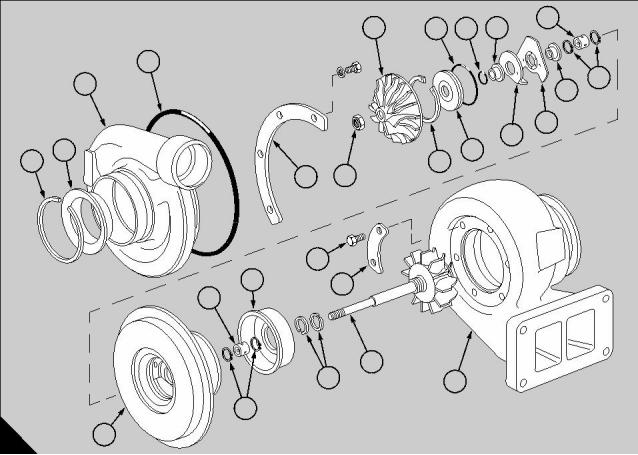
18
13 Use two flat screwdrivers to gently remove the oil
seal plate (A9).
14 Remove the oil slinger (A12) and and remove and
1
1
discard its piston ring seal (A11).
15 Remove and discard the ‘O’ ring seal (A10).
16 Remove the oil baffle (A13).
17 Remove the thrust bearing (A14) and the thrust
collar (A15).
18 Remove and discard the two circlips (A16) and
withdraw the journal bearing (A17).
19 Turn the bearing housing over. Remove and
discard the two circlips (A19) and withdraw the journal
bearing (A20).
A
160
10 Fit the oil baffle into the housing.
To assemble
11 Fit a new piston ring to the oil slinger and insert it
Before assembly, ensure that the compressor wheel
and the turbine shaft/wheel have both been
into the oil seal plate.
individually balanced by an establishment having the
relevant special equipment and knowledge. The two
parts must then be assembled and balanced. During
balancing, the alignment marks on the end of the
shaft and the compressor wheel MUST be aligned.
12 Fit the oil seal plate into the bearing housing.
Ensure that the balance marks on the oil slinger are
aligned with those on the end of the shaft. Gently tap
the oil seal plate with a soft-faced hammer to seat it
fully.
1 Place the turbine housing on a flat bench with the 13 Use circlip pliers to fit the circlip.
turbine end uppermost. Fit the circlip with its bevelled
edge facing upwards.
14 Align the balance marks and fit the compressor
wheel onto the shaft. Fit the compressor wheel lock
Caution: Circlips (A1) must always be fitted with the nut (left-hand thread). Tighten to a torque of 17 Nm
bevelled edge facing the journal bearing.
(150 lbf in).
15 Secure the turbine housing in a vice or suitable
fixture. Fit the bearing housing assembly to the
turbine housing. Fit the three clamp plates, align
the scribe marks and tighten the six bolts to a
torque of 20 Nm (180 lbf in).
16 Position a dial test indicator so that its plunger is
resting on the end of the shaft. Check the end float of
the shaft between the extreme positions.
2 Lubricate the journal bearing and fit it into the
bearing housing. Fit the second circlip with its
bevelled edge facing the bearing.
3 Turn the turbine housing over and repeat the
procedure with the other journal bearing and circlips.
4 Fit the heat shield.
5 Fit new piston ring seals (A22) to the turbine shaft.
Fit them with their gaps 180 degrees apart as shown
in the illustration (A) on page 112.
Total travel should be between 0,038 mm to 0,093 mm
(0.0015 to 0.0037 in).
6 Lubricate the turbine shaft and fit it into the bearing
17 Mount the dial test indicator gauge with its plunger
resting on the side of the shaft above the compressor
wheel and check the extreme radial travel by pushing
the impeller towards and away from, in turn, the dial
test indicator.
Total travel should be between 0,394 mm and
0,635 mm (0.0155 to 0.0250 in).
housing.
Caution: The piston ring seals MUST be fitted with
their gaps 180 degrees apart. Gently press down on
the turbine wheel and rotate it slightly to assist with
properly locating the piston ring seals.
7 Support the assembly in a suitable fixture and fit the
thrust collar. Ensure that the balance mark on the
thrust collar is aligned with that on the shaft.
Note: Readings outside the acceptable travel limits
in paragraphs 16 or 17 will indicate that a complete
overhaul is necessary or that a service replacement is
required.
8 Apply a light coat of engine oil to the thrust bearing
and fit it to the bearing housing.
9 Apply a small amount of clean engine oil to the ‘O’
18 If fitted, install the ‘O’ ring seal.
ring seal and fit it into the housing.
Continued
Perkins Engines Company Limited
113
This document has been printed from SPI². Not for Resale
![]()
![]()
18
19 Fit the compressor housing and align the scribe
marks. Take care not to damage the compressor
wheel. Fit the two clamp plates and secure with eight
bolts and locking washers, where relevant, fit the
cylinder of the waste-gate assembly. Tighten the bolts
to a torque of 8.5 Nm (75 lbf in).
7 Check the compressor housing for damage caused
by possible contact with the rotor. Slight damage is
acceptable but otherwise the housing should be
replaced. Check the condition of the ‘V’ band groove.
8 Inspect the oil slinger (A12). Ensure that the walls
of the seal grooves are not scored or damaged. Also
check for signs of rubbing on the flat surfaces.
20 When fully assembled, check by hand that the
rotor spins freely.
9 Inspect the bore of the oil seal plate (A9), renew if
21 Bend over the tabs of the locking plates on the
scored or damaged.
turbine and compressor housings.
10 Inspect the heat shield (A21), renew if there are
22 Where necessary, fit the inlet baffle and its
signs of distortion, rubbing or cracks.
retaining ring to the compressor housing.
To clean and to inspect
18-8
To clean
1 Use a commercially approved non-caustic cleaning
solution to soak parts until all deposits have been
loosened. Bead blasting may be used on the turbine
housing, but only if chemicals do not clean
sufficiently.
Caution: Do NOT use bead blasting on any other
turbocharger components.
2 Clean all aluminium parts with a bristle type brush
or plastic scraper. Vapour blast may be used except
on the shaft and bearing surfaces.
Caution: Do NOT use a wire brush or metal scraper
on any turbocharger component.
3 Blow compressed air through all drilled
passageways and ensure that the surfaces adjacent
to the turbine and compressor wheels are clean,
smooth and free from deposits.
To inspect
1 Inspect the shaft bearing journals and the walls of
the seal grooves for wear and excessive scratches.
Minor scratches may be tolerated.
2 Check the turbine and compressor wheels for
cracked or damaged blades but do NOT attempt to
straighten blades.
3 Check the thrust bearing surfaces for wear or
damage. Minor scratches are acceptable. Ensure that
the feed grooves in the thrust bearing are clean.
4 Replace the bearings if excessively scratched or
worn.
5 Renew the bearing housing if the bearing or seal
bores are severely scratched or worn. Ensure that the
tapped holes are clean.
6 Check the profile in the turbine housing for damage
caused by possible contact with the rotor. Inspect the
outer and inner walls for cracks or flaking caused by
overheating, also check the mounting flanges for
signs of distortion.
114
Perkins Engines Company Limited
This document has been printed from SPI². Not for Resale
![]()
![]()
![]()
![]()
18
Inlet manifold
Exhaust manifold
To remove and to fit
18-9 To remove and to fit
18-10
Note: References to coolant drain and refill, and to
removal of the coolant pipes, ONLY apply when an
engine is fitted with an air-to-coolant charge cooler.
To remove
1 Remove the boost control pipe from between the
fuel injection pump and the air intake pipe.
To remove
2 Disconnect the air intake pipe from the
turbocharger and remove it from the engine.
1 Drain the engine coolant.
3 Disconnect the oil feed and drain pipes from the
2 Disconnect and remove the coolant pipes from both
turbocharger.
ends of the charge cooler casing.
4 Remove the bolts and clamps securing the
manifold to the cylinder heads, and withdraw the
assembly. Make a note of the position of the clamps
and bolts to assist when refitting.
3 Remove the bolts securing the air intake pipe to the
manifold. Discard the gasket.
4 Where necessary, remove the compressor air
intake filter.
5 If necessary, separate the turbocharger from the
5 Remove the bolts and washers which secure the
manifold to the cylinder heads. Remove the manifold
and discard the gaskets.
manifold.
To fit
To fit
1 Always use new gaskets and ensure that all joint
faces are clean.
1 Renew all gaskets and ensure that all joint faces
2 Fit and secure the manifold to the cylinder heads
are clean and undamaged.
with the relevant bolts, washers and plates.
2 Fit and secure the manifold to the cylinder heads
with the relevant bolts and washers. Tighten the bolts
evenly.
3 Tighten the bolts evenly to a torque of 45 Nm
(33 lbf ft).
4 Fit the turbocharger to the manifold if it was
3 Fit the air intake pipe to the manifold, renew the
separated on removal.
gasket and tighten the bolts securely.
5 Fit the air intake pipe.
6 Fit the boost control pipe.
4 If relevant, fit the compressor air intake filter.
5 Fit the coolant pipes to the charge cooler casing.
6 Refill the coolant system with the recommended
coolant mixture.
Perkins Engines Company Limited
115
This document has been printed from SPI². Not for Resale
![]()
![]()
![]()
![]()
![]()
![]()
This document has been printed from SPI². Not for Resale
19
Lubrication system
19
General description
The engine has a wet sump type system. One of two
types of sump is fitted: a cast aluminium type or, for
recent engines, a version made from a composite
material. The capacity of the aluminium sump is 25
litres (5.5 UK gallons) to the maximum mark on the
dipstick and 18 litres (4 UK gallons) to the minimum
mark. The capacity of the composite sump is 41 litres
(9 UK gallons) to the maximum mark on the dipstick
and 34 litres (7.5 UK gallons) to the minimum mark.
The drain plug fitted to the sump depends on the type
of engine.
Continued
Perkins Engines Company Limited
117
This document has been printed from SPI². Not for Resale
![]()
![]()
19
The oil is circulated in the system at a pressure of 310
to 480 kN/m² (45 to 70 lbf/in²). Pressure is controlled
by a relief valve assembly (A3) contained in the body
of the oil pump (A2). The oil pump is mounted on the
front main bearing cap and is driven by a large spur
gear on the front of the crankshaft.
Key to illustration (A)
1 Suction filter
2 Pressure pump
3 Oil pressure relief valve
4 Oil cooler
Oil is drawn by the oil pump through a strainer (A1),
and is delivered, under pressure, to the oil cooler
(A4), the base of which forms the oil filter header
bracket.
5 Parallel-flow main filters
6 Piston cooling jets
7 Supply to turbocharger
8 Supply to injection pump (early engines)
9 Idler gear axle
After being cooled by the engine coolant, the oil
passes through the two canister type filters (A5) which
incorporate filter by-pass valves.
The filtered oil is then directed into the transfer pipe
which returns the oil to the main oil gallery which is
machined in the crankcase.
High pressure system
Drillings in the crankcase provide lubrication for the
camshaft and crankshaft bearings. The crankshaft
shown (A) is of the early type which included an oil
reservoir within each crankpin. The crankshafts of
engines built after July 1995 have a new arrangement
of oil passageways which removes the need for oil
reservoirs.
Restricted flow system
Suction spill and splash lubrication
A
118
Perkins Engines Company Limited
This document has been printed from SPI². Not for Resale
![]()
![]()

19
Two oilway studs in the top face of the crankcase
allow the passage of oil for lubrication of the rocker
gear, push rods and tappets.
Individual drillings from the main gallery supply oil,
under pressure, to the piston cooling jets. The jets,
fitted with an ‘O’ ring type seal, are fitted to the
underside of the main oil gallery. Oil flow from the jets
is continuous when the engine is running and is
directed at the inside of the piston.
The idler gear axle and bearing are supplied with oil
under pressure from the main gallery, with the gear
train being splash lubricated.
Oil to the fuel injection pump passes through drillings
in the mounting plate and backplate and returns to the
sump through a drain hole at the front of the pump.
For recent engines, lubricating oil is supplied to the
fuel injection pump by an external flexible pipe
connected to the main oil gallery of the crankcase.
Oil is delivered to the turbocharger bearings through
a steel pipe from the engine system and returns to the
sump through a flexible drain pipe.
Certain engines are fitted with an oil by-pass filter.
The by-pass filter uses centrifugal force to remove
particles from the oil. After the oil has passed through
the filter it is returned to the sump. The by-pass filter
is fitted in addition to the main oil filter canisters NOT
instead of them.
Perkins Engines Company Limited
119
This document has been printed from SPI². Not for Resale
![]()
![]()
19
Lubricating oil filter
Two canister type filters are fitted to a header which is
part of the oil cooler. Each canister incorporates a
filter by-pass valve which allows a continuous flow of
oil should the element become blocked.
To renew the canister
19-1
Special tools:
Strap wrench, 21825 825
1 Put a tray under the canisters and use a strap
wrench, 21825 825, to remove each canister (A1).
2 Check that the sealing rings are correctly fitted to
the new canisters and clean the contact faces of the
filter head.
3 Fill the two new canisters with new engine
lubricating oil of the correct grade and lubricate the
top of each canister seal with the same oil.
4 To install the new canisters use this procedure:
1
Tighten the canisters, on their adaptors, until the
sealing rings are in contact with the face of the filter
1
head, then turn the canisters a further 1 / turns, by
4
hand. Do NOT overtighten.
A
171
120
Perkins Engines Company Limited
This document has been printed from SPI². Not for Resale
![]()
![]()
![]()
![]()
![]()
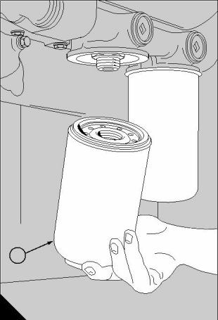
19
By-pass filter/separator
1
This filter is only fitted to certain engines. It is used in
conjunction with the main lubricating oil filters. It is
NOT an alternative. The filter must be serviced at the
intervals specified for engine oil and main filter
changes.
2
To renew the canisters
19-2
3
1 Clean the area around the by-pass filter. Remove
the filter bowl (A2), remove and discard the rotor (A3).
2 Remove the seal (A4) from the filter bowl and clean
all the components, especially the recess for the seal
in the filter bowl and the contact face for the seal on
the housing.
4
3 Fit a new seal to the recess in the filter bowl and
lubricate the face of the seal with clean engine
lubricating oil.
4 Fit a new rotor to the spindle and ensure that it can
rotate freely. Fit the filter bowl and tighten the nut (A1)
to a torque of 20 Nm (15 lbf ft).
5 When the engine is operated, check for leakage
from the by-pass filter.
A
07
Perkins Engines Company Limited
121
This document has been printed from SPI². Not for Resale
![]()
![]()
![]()
![]()